


For Drivers, Mechanics, and Foremen.
Page 21
If you've noticed an error in this article please click here to report it so we can fix it.
We revive this popular "C.M." feature in connection with our "Keep Your Lorry Fit" Series, and offer a prize of ONE GUINEA for the best communication concerning any chassis to which reference has been made in that series.
Other letters on subjects of interest will be paid for on publication at the rate of One Penny a Line, and failing any award of the above prize, TEN SHILLINGS will be paid for the best letter published each week. Mention your employer's name, in confidence, as evidence of good faith. Address D., M, and if., " The Commercial Motor," 7-15, Bosebery Avenue, London, E.G.
Lamps Alight.
On Saturday, lath November, light your lamps at 436 in London, 4.29 in Edinburgh, 4.27 in Newcastle, 4.40 in Liverpool, 4.39 in Birmingham. 4.46 in Bristol, 4.58 in Dublin.
Centring a Shalt.
[1684] " A.E." (Holloway) writes:—" I have designed a cheap tool by the aid of which the centre of a shaft may readily be found. It consists merely of a. piece of sheet steel bent at right angles ; its size depends upon the shaft diameter' and may be judged by reference to the sketch which I enclose [We have had this redrawn.—End. The portion which overlaps the shaft may be a little deeper or a little shallower than the radius. Both of the long edges should be perfectly straight. If one arm of the angle be made a little longer than the other, a greater number et sizes of shafts May be centred by its aid. Each side, of course, will do for several sizes, the radius of which may be a little greater or less than the depth of the overlapping portion of the tool. In use, the piece of sheet steel is placed in position as shown on the left-hand sketch, a line is scribed, and the tool turned round a little when a second line is drawn, and so on until the end of the shaft is crisscrossed with lines as shown by the right-hand sketch ; the centre is, of course, in the centre of the small circle which will be formed by the intersection of these lines. The nearer the depth of the overlapping piece is to the radius of the shaft, the smaller will this circle be, and more accurately will the centre be found."
Repairs to Square-thread Nuts.
[1685] " J.M.A.Y." (Luton) writes :—"Nuts for square or buttress thread bolts-, such as those in use for the traversing gear of lathes, may be readily repaired when worn in the following way, which has the advantage that it obviates any necessity for screw-cutting m the lathe. "In the enclosed sketch [We have had this redrawn.—En.] I show a nut for a cross slide on a lathe which is worn. This should be put in the lathe, and all but a thread or two at each end bored out. Two large holes are drilled in the outside of the nut and countersunk. The screw should then be threaded through so as to protrude at both ends of the nut. "Pack each end of the n-ut with clay and heat well. Into one of the holes then pour white metal quickly ; the other hole serves as an outlet for the air and to show when sufficient metal has been poured in. When the white metal cools it will then be possible to take out the screw, and a. good job will have been made of the repaired nut."
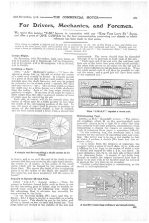
How " J.M.A.Y." repairs a worn nut. Withdrawing Tool.
[1686],".A.H.H." (Llandaff) writes :—" The univeesal..coupkngs which fit on the gearbox-shaft ends genemlly require to be a tight fit in order that they may properly fulfil their purposes consequently, when dismantling a chassis for repairs or overhaul, the work of removing these parts is sometimes difficult. "In the ordinary way, the mechanic uses a lead hammer for the purpose of separating shaft and coupling. The better way is to use a tool similar to that of which I enclose a sketch [We have had this redrawn.—En.]. "It is made from the simplest of materials, the crossbar being a pieoe of steel plate, 2i in. wide and in7deep by 6 in. long, in the centre of which a hole is drilled and tapped to take a I in. set screw. At equal distances, say, 211 in., on each side of this I drill in. clearance holes. A couple of eye bolts long enough to enable the largest universal joint that is likely to be met with to be tackled must be screwed in placerin the two holes in the crossbar. Further verbal-description is unnecessary, as the sketch is self-explanatory."