


Gas Producer Using Oil Fuel
Page 48
If you've noticed an error in this article please click here to report it so we can fix it.
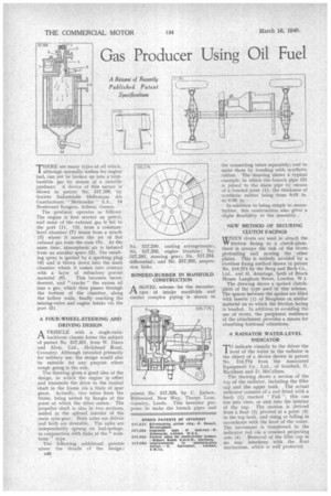
A Résumé of Recently Published Patent Specifications THERE are many types of oil which, although normally useless for engine fuel, can yet be broken up into a combustible gas by means of a suitable Koducer. A device of this nature is shown in patent No. 517,399, by Societe Industrielle Hellenique des Gazofacteurs " Berhoudar " S.A., 14 Boulevard Syngros, AthenS, Greece.
The producer operates as follows: The engine is first started on petrol, and some of the exhaust gas is led to the port (1). Oil, from a constantlevel chamber (7) issues from a nozzle
(3) where it meets the jet of hot exhaust gas from the cone (8). At the same time, atmospheric air is induced from an annular space (2). The resulting spray is ignited by a sparking plug (4) and is blown down into the main chamber where, it comes into contact with a layer of refractory porous
material (6). This becomes incandescent, and " cracks " the excess oil into a gas, which then passes through the bottom of the chamber, along the hollow walls, finally reaching the mixing-valve and engine intake via the port (5).
A FOUR-WHEEL-STEERING AND DRIVING DESIGN .
A VEHICLE with a single-tubePI backbone chassis forms the subject of patent No. 517,281, from W. Dunn and Alvis, Ltd., Holyhead Road, Coventry. Although intended primarily for military use, the design would also he suitable for any purpose where rough going is the rule.
The drawing gives a good idea of the design, in which the engine is offset and transmits the drive to the central shaft in the frame via a train of spur gears, Actually, two tubes form the frame, being united by flanges at the point at which the drive enters. The propeller shaft is also in two sections, united in the splined interior of the main spur-gear. Both axles are driven and both are steerable. The axles are independently sprung on leaf-springs, in conjunction with links of the " wishbone " type.
The following additional patents cover the details of the design: A46 No. 517,280, cooling arrangements; No. 517,282, engine location ; No. 517,283, steering gear; No. 517,284, differential; and No. 517,292, suspension links.
BONDED-RUBBER IN MANIFOLD CONSTRUCTION
ANOVEL scheme for the manufacture of intake manifolds and similar complex piping is shown in
patent No. 517,325, by C. Judson, Riftswood, New Way, Thorpe Lane, Guiseley, Leeds. This inventor proposes to make the branch pipes and
the connecting tubes separately, and to unite them by bonding with synthetic rubber. The drawing shows a typical . example, in which the branch pipe (2) is joined to the main pipe by means of a bonded joint (1,), the thickness of synthetic rubber being from 0.01 in. to 0.05 in..
In addition to being simple to manufacture, this construction also gives a slight flexibility to the assembly.
NEW METHOD OF SECURING CLUTCH FACINGS WHEN rivets are used to attach the W friction facing to a clutch-plate, there is always the risk of the rivets protruding and scoring the other plates. This is entirely avoided by a rivetless fixing method shown in patent No. 516,274 by the Borg and Beck Co., Ltd., and H. Armitage, both of Brock House; Langham Street, London, W.I.
The drawing shows a spoked clutchplate of the type used in this scheme. The spaces between the spokes are Mled with inserts (1) of Neoprene or. similar material on to which the friction facing is bonded. In addition to avoiding the use of rivets, the peripheral resilience of the attachment provides a means for absorbing torsional vibrations.
A RADIATOR WATER-LEVEL INDICATOR
'TO indicate visually to the driver the 1 level of the water in the radiator is the object of a device shown in patent No. 516,774 from the Associated Equipment Co.. Ltd., of Southall, G. Rackham and D. McCallum.
The drawing shows a section of the top of the radiator, including the filler cap and the upper tank. The actual indicator consists of a rod fitted with a knob (1) marked "Full "; this can rise into view, or sink into the interior of the cap. The motion is derived from a float (2) pivoted at a point (3) in the top tank, and rising or falling in accordance with the level of the water. The movement is transferred to the indicator rod via a cranked projecting arm (4). Removal of the filler cap in no way interferes with the float mechanism, which is well protected. .