


Patents Completed.
Page 22
If you've noticed an error in this article please click here to report it so we can fix it.
Complete specifications of the following patents will be sent to any address in the United Kingdom '2 upon receipt of eightpence per copy at the Sale Branch, Patent Office, Holborn, W.C. 4;1
MORSE CHAIN. — Morse. — No. 13,397/10, dated under International Convention, 28th January, 1910.--A construction of Morse chain is described in this specification which enables the links to be produced horn a continuous bar by a single cutting operation. The link consists of a head-piece, preferably of the silent type, adapted to engage the straight-sided teeth of a sprocket wheel, and a pintle portion rigidly or integrally connected to the head by an arched-over portion, the head portion having a transverse socket adapted to form a bearing for the pintle portion. In order to secure the links together, the pintle portion may be drilled through for a rivet, and the ends of the soeket in the head portion are countersunk to provide recesses for the washers on the rivets. One of the methods described for fastening the links is illustrated in the accompanying figure. The inner end of the hole in the pintle is enlarged, and rivet pins having a coneshaped recess at the inner end are provided. These pins are secured in place by inserting a steel hall in the hole and driving the pin against the ball, the end is thus upset to 5.11 the enlarged bore, and the rivet is thereby secured in position. If desired, this upsetting may be done at one operation with the rivetting of the upper end of the pin, thus providing a simple and cheap method of fastening the links together.
CARBURETTER. — De Beer. — No. 3,501, dated 12th February, 1910.—The object of this invention is to provide a carburetter which is simple and at the same time capable of being readily ad justed to the requirements of any engine within practical limits. The float chamber and jet chamber are connected together in the usual manner, and within the jet chamber there is provided an inner rotatable sleeve formed in two parts, rotating one within the other. The outer sleeve is the shorter, and is
provided with a circular hole controlling the air inlet. The inner sleeve is provided with a pear-shaped orifice in the lower portion and also with a circular orifice controlling the outlet pipe to the engine. The outer sleeve is adjusted to the position for giving the maximum-air inlet. The inner sleeve provides a more delicate control of the air supply by varying the opening in the outer sleeve. There is also described in the provisional specification an arrangement whereby a mechanically-operated tap or cock is arranged between the float and jet cham. bars, which, when closed, cuts off the fuel supply from the jet chamber, allows the engine to run free and retains in the float chamber the fuel for restarting the engine.
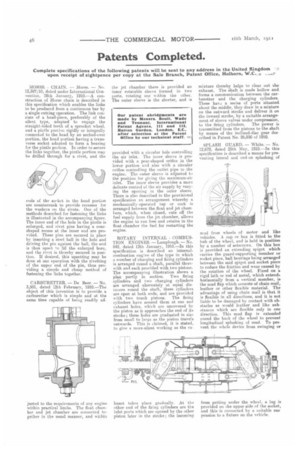
ROTARY INTERNAL COMBUSTION ENGINES. — Lamplough. —No. 842, dated 12th January, 1910.—In this specification is described an internalcombustion engine of the type in which a number of charging and firing cylinders is arranged round a shaft, parallel therewith and each provided with two pistons. The accompanying illustration shows a plan partly in section. Two firing cylinders and two charging cylinders are arranged alternately at equal distances round the shaft, these cylinders are open at both ends, and are provided with two trunk pistons. The firing cylinders have around them at one end exhaust holes, which are uncovered by the piston as it approaches the end of its stroke ; these holes are graduated in size from small to large as the piston travels outwards. This is claimed, it is stated, to give a more-silent working as the ex haust takes place gradually. At the other end of the firing cylinders are the inlet ports which are opened by the other piston later in the stroke ; the incoming
mixture thereby helps to clear out the exhaust. The shaft is made hollow and. forma a communication between the carburetter and the charging cylinders. These have a series of ports situated. about the middle, they draw in a mixture on the outward stroke and deliver it on the inward stroke, by a suitable arrangement of sleeve valves under compression, to the tiring cylinders. The power is transmitted from the pistons to the shaft by means of the inclined-disc gear described in Patent No. 26990 of 1910.
SPLASH GUARD. — White. — No. 12,672, dated 25th May, 1910.—In this specification is described a means for preventing lateral and end-on splashing of mud from wheels of motor and like vehicles. A cap or box is fitted to the hub of the wheel, and is held in position by a number of setscrews. On this box is provided an extending spigot which carries the guard-supporting member or socket piece, ball bearings being arranged between the said spigot and socket piece to reduce the friction and wear caused by the rotation of the wheel. Fixed on a rigid lath or rod of metal, which extends horizontally from a vertical member, is the mud flap which consists of chain mail, leather or other flexible material. The advantage of using chain mail is that it is flexible in all directions, and it is not liable to be damaged by contact with obstacles as would leather and like substances which are flexible only in one direction. This mud flap is extended round the back of the wheel to prevent longitudinal splashing of mad. To prevent the whole device from swinging 07 from getting under the wheel, a lug is provided on the upper side of the socket, and this 'is connected by a suitable sns. pension to a fixture on the vehicle.