


Albion
Page 7
Page 8
Page 9
If you've noticed an error in this article please click here to report it so we can fix it.
In view of the fact that so many irritating stops on the road with ii H types of vehicles are traceable to .choked petrol jets, and even in spite of the provision of carefullydesigned filters, it is good practice to ensure, at, reasonable intervals, that all the. petrol pipes are quite clear. They should be detached for this purpose and blown through, in order to insure their cleanliness.
Combined Fan and Pump Drive.
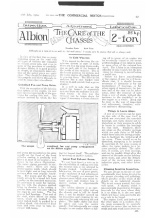
With the exception of the lubrication system of the engine, we now only have to write briefly of the pro vision for cooling tins unit. The neique, method by which the fan
and pomp are mounted on the same spindle on the front of the front cylinder casting is probably well know n to most of our readers ; it is shown in the above illustration. The water piping generally is sun: plieity itself ; there are three rubber-canvas joints which should be kept tight, and at long intervals perhaps they may require renewing. The pump and the fan are jointly driven by a. broad belt from a pulley on the camshaft extension. No provision is made for tightening the belt, the obvious method being to shorten it by cutting a portion from one end and refixing
the clips in new holes. The fan runs on ball hearings. That end of the shaft which drives the pump vanes, which are located in the water jacket itself, is packed by a stuffing gland ; this should be kept light and from time to time repacked with hemp. In Cold Weather.
With regard to draining the circulation system in case of frost, there are two big plug drain-cocks, one on each side of the bottom of the inside of the radiator. This is the lowest point on the system, and the water can be effectually drained by opening them. The filler in the radiator has a cast bucket with holes in it, and outside that a gauze strainer.
it is well to note that on this model the bonnet, is separately mounted from the radiator on a distinct frame. In this way the radiator can be taken down for repair if necessary without disturb ing the bonnet itself. The radiator is mounted on rubber buffers.
About Foul Exhaust Boxes.
We may here insert a note as to the advisability of making sure that the exhaust box is not allowed to become choked. Accidental overlubrication, the use of poor petrol, or the existence of had adjustment of the fuel supply, are amongst the circumstances which may cause exhaust pipes and exhaust box to secrete carbon in objectionable quantities.
The Albion silencer is as carefully designed as any other unit on the chassis, and it will be found that it can be readily opened up for inspection and cleaning by unscrewing the nuts retaining the end plates. The baffle plates can then be taken out. -e ith the centre spindle. Not infrequently are cases brought to our notice where a. fall ing off in poweiof an engine can be eventually traced to the unsuspected choking of the exhaust pipe, or more often of the exhaust box itself. The Albion is an infrequent offender in this respect, but the provision for cleaning is, nevertheless, a useful one.
Before we leave consideration of the engine, it may be well to indicate that, if it. should become necessary to dismantle it for the replacement of bearings, or for other repair of importance, the bottom half of the case can be taken away, after the removal of nuts from a row of studs, without disturbance to the crankshaft or to the engine as a whole. Much can be done in the way of inspection and adjustment, therefore, without extensive dismantling.
Things to Leave Alone.
A row of set-screws can be seen on that side of the case itself in which are contained the camshaft housings, and these should not be disturbed, as their purpose is solely to locate in position the bearings for that shaft. Similarly, there are plugs on the cylinder castings which are only there to fill holes which have been left during production to facilitate the withdrawal of the cores. These. should never be disturbed, excepting it be desired to ascertain if, for some reason or other, the water jackets have become partially choked. The cylinders, of couise, are twin castings, and can be readily -lifted after the removal of the nuts on the holdingdown studs, and .after the detachment of the various water pipes, induction pipes, and other accessories.
Cleaning Involves Inspection.
We are always in favour of very considerable time being devoted to the proper cleaning and polishing, where possible, of the whole of the details on an industrial chassis. This is not money wasted, but time well spent. A chassis, which is unconsciously inspected at. frequent, intervals by the man whose duty it is to clean it is the one upon which few loose nuts and bolts are as a rule to be found.
The engine itself, and indeed all the other units on a modern chassis, must necessarily be carefully watched to ensure that no bolts or studs and nuts work loose from ono
cause or another. Neglect to ensure that these are kept -Qat up to their work is a more fruitful cause of rapid depreciation of the whole machine than any other factor that occurs to us.
A Single-plate Clutch.
The next unit for consideration in this article is the clutch, which is of the single-plate type. One of our illustrations shows its general form. We need not trouble our readers with any close technical description of this well-tried unit ; it is of a class which gives very little trouble indeed in practice. The wear on the surfaces proves to be, in ordinary use, almost negligible.
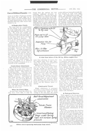
Engagement is effected by the action of the series of springs housed in the outer case, which, when allowed to do so, press a softsteel-plate between two Ferodolined discs. A simple arrangement of lever mechanism neutralizes the pressure of these springs and so allows the centre disc to run free. The latter is, of course, mounted on an extension of the main drive, which runspclear through the outer casings of the clutch proper, its inner end riding on a spherical bearing, which is located on an extension of the crankshaft.
Clutch-thrust Adjustment. The thrust of the withdrawal ring is taken by a hall race, svhich is centrally mounted just behind the actuating collar. This ball bearing is adjusted by a screwed coliar, which is locked in position I., a suitable setscrew. Adjustment at this point should very rarely be necessary, The pull on the flywheel, when the clutch is withdrawn, is taken on a ball thrust Washer at the front of the crankshaft, so that the crankshaft bearings are free from all end thrust, whether the clutch be in or out.
When the Clutch Slips.
At such time when the clutch linings have worn thin, it may be found that the springs are not exerting sufficient pressure to -secure adhesion ; this can obviously be remedied very simply by the filling up of the spring caps with packing discs of sheet metal or any other handy material, care being taken that this be not done sufficiently to neutralize the effect of the springs by locking the coils together, at the same time allowing, of course, lty. the motion that must take place when the springs are compressed during clutch withdrawal. Whenever' the need arises to remove the big hexagon caps holding the springs in position, care should be taken that when replaced they are screwed up hard again. This is, however, only a temporary expedient., and when the linings have worn to this extent, new ones should be fitted. For this purpose, the clutch may be taken to pieces with facility, the propeller shaft being first disconnected and taktn down, and the distance piece removed.
Clutch-pedal Travel.
Slight adjustment is necessary from time to time before the linings have reached this stage of wear, owing to the fact that the clutch pedal will have lowered towards the foot boards as such wear takes place. An illustration on page 4D:3 shows the provision which is made on this pedal for readjusting its actual travel. The pedal itself is a loose piece mounted separately on its fulcrum portion, and held in position by a bolt and nut located in the slotted hole in the lower por tion. Air adjustment setscrew fixes its position, and this may be then again tightened. The amount of rise permissible on the pedal is located by another small setscrew, which butts against the big cross tube which is immediately behind the pedal shaft. All this arrangement is clearly shown in our sketch. If slipping take place in the clutch, care should be taken to ascertain that these adjustments are not holding the plates out of engagement, owing to improper setting. There is little requiring attention in respect of the propeller shaft. From time to time it should be assured that the setscrew which holds the coupling in position is properly fixed, but this should not be touched in the ordinary way. The lubrication of these joints is dealt with elsewhere.
A Fool-proof Gearbox.
With regard to the change-speed gearbox, providing it he used with something like commonsense, this again will require little more attention other than regular lubrication and the periodic draining of the old oil and replacement of it with new. There are oil catchers over all the bearings, which ensure the proper and automatic distribution of the lubricant.
It is wise to inspect the interiors of the two parts of the box, say, at intervals of every thousand miles, and then to make certain that all the nuts holding the caps in position, and all the pins and forks, are tight, and that nothing has worked loose ; this is merely a precaution, but it is one that is sometimes neglected, owing to the immunity of a box like this' from serious trouble.
Care of Albion Chassis—con, Meshing the Gears.
The reduction from the gearshaft to the differential shafts in this model is effected by a worm gear, the thrust from which is taken up by suitable ball bearings adjusted in position when the box is assembled. It may be necessary from time to time to ascertain that these are doing their work, and that no
back lash has developed. If the
lime arrives when it is necessary to dissemble the gearbox for replacement of any important part, it will by yell to ascertain that the gears mesh correctly for the definite fixed positions as set by the change-speed lever and its gate. If these locations, for some reason or other, are not correct before re-assembly, the front ends of the two selector rods may be adjusted to secure perfect alignment.
An interesting addition to the gearbox mechanism, on the chassis from which particulars wereobtained for this article, was a mileometer, mounted on the gearbox, with its own driving gear embodied inside the box. This position may ii ,een in the illustration opposite.
Keep the Drain Plugs Tight.
The usual stipulation with regard to periodic inspection of all bolts trtd nuts on this unit, of course, holds good for other parts of the chassis. We would advise that from time to time it be noted that the plug at the bottom of the case, whieh is used for draining purposes, has been screwed up tight. We have known occasions on various types of chassis where careless drives have replaced a plug of this kind improperly, so that it has dropped out, and the box has been run without, lubricant for a considerable period.
Test the Dill. Gear.
With regard to the differential gear, it is well, at intervals of every thousand miles, shall we say, to leek up eaelg wheel in ',urn. and to
note that it can be revolved with comparative freedom, providing that the chain adjustment be colmeet.
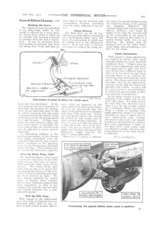
Chain Pinions. The final drive on the '25 h.p. Albion is by side chains, running in cleverly-designed chain cases, the form of construction of which can be clearly seen in the illustration below. If at any time it become necessary to replace the chain pm
ions, which are mounted on the outer ends of the differential shafts, it must be ascertained that the taper of the pinion bore is identical with that of the shaft end. If they are not exactly .correct, they should he rubbed in with emery and oil aintil a good seating is obtained. It is a sine ono non that the keys be a tight fit in the sides of the keyways, but not in respect of their depth. for fear that jamming in this dintensitm ntight prevent the taper's going right home.
Removal of a pinion is effected
by means of a special extractor tool, for which the bosses of the pinions are adapted. Whatever the method adopted of withdrawing the pinion, however, care must be taken to see that the screwed end of the cross-shaft is not injured. When the faces of the teeth on a pinion become badly worn in one direction, the pinion may be changed over to the other differential shaft, thus presenting a new face for the chain.
Chain Adjustment.
With regard to chain adjustment, we cannot do better than quote from the Albion Co.'s own excellent handbook thus "Chains must be kept in such adjustment, that when the upper part is tight, the lower part should have sufficient slack to allow it to be moved up and down through about 1 in., midway between the chain wheel and the chain pinion. The chains must not be kept too tight-they can be tightened to such an extent, that the engine will not drive the vehicleor there will be a loss of power ; nor should they be allowed to get too slack, or they may jump the chain pinions."
As the chains stretch in wear, adjustment. of the radius rods to suit must take place. No chain should be used that has stretched more than 2 ins, for the average length on a standard Albion two-tonner. When it vehicle is running with badly-stretelted chains, it is always advisable to carry a spare one, in case replacement may become necessary on the road. Care should be taken in all chain-driven vehicles that when adjustment is made to the find drive, both radius rods are adjusted equally, otherwise the track alignment of the back wheels is deflected.