


Overcoming Twisting Stress in Road-borne• Tanks
Page 50
If you've noticed an error in this article please click here to report it so we can fix it.
AODERN tankers usually have their IV/ tank made of light steel or aluminium alloy, supported by a number of strapped or welded bearers. Although the latter are usually bolted to the frame upon rubber blocks, they are often subjected to twisting stresses. To eliminate these is the object of an improved mounting shown in patent No. 592,277. by R. Hulse and the Steel Barrel Co., Ltd., Phenix Wharf, Uxbridge. •
The tank is -mounted on the usual bearers (1), but the latter are supported on the frame at one central point at the rear and two or more points at the side. The side points carry spring mountings t2), which can provide resilience when the frame twists. The drawing shows this condition, in wh,ch one spring is ab more highly compressed than the other. Hydraulic supoorts„operating similarly, are also mentioned as an alternative.
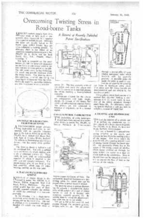
EPICYCLIC HUB-REDUCTION GEAR FOR DUMPERS
A TRANSMISSION design embody
ing high-speed half-axles, in conjunction with an epicyclic reduction gear in the hub is shown in patent No. 591,475, by J. Abbott and Motor Rail, Ltd., both of Simplex Works, Bedford. The scheme is illustrated as applied to a dumper, but has many other applications.
The drawing shows a half-axle and its associated hub. The axle is splined to a sun-wheel (1), which meshes with a set .of planetary pinions (2). These mesh, in turn, with an outer-toothed annulus (3) which is attached to the axle tube and remains stationary. The planet-carrier pins (4) are fixed to the hub assembly, which mita on roller bearings centred on the axle tube.
• A FLAT FOUR-CYLINDERED ENGINE NjOYELTY Jr). engine design is dis1 closed in patent No. 529,036, by I. Wooler, Willow Bungalow, West End
Road, Ruislip, Middlesex. The proposed engine has two pairs of horizontally opposed cylinders, the pistons of which are connected to a common icrankpin.
In the drawing, I is a single-throw crankshaft which carries the master connecting rod in the usual way. The rod is pivoted to an intermediate triangular member (2) which can rock about a *40 centre (3). The two opposite arms of the rocker each carry two piston rods (4 and 5) connected to opposed pistons. the whole forming a four-cylindered assembly.
Advantages claimed for the scheme are compactness and light weight, mainly on account of the closely 'balanced and self-contained opposed forces. The pistons are not subjected to extremes of angularity, as in a normal engine.
GAS-CUM-PETROL CARBURETTER THE desirability of using home-produced fuels lends interest to a carburetter shown in patent No. 591,685, by Societe NationAle de Constructions Aeronautiques du Centre, of Paris. The carburetter described functions as a gasmixing valve, but petrol also can be passed when a power boost is needed.
The drawing shows a section illustrating the scheme, a variable-area choketube which consists of a pair of rotary barrels (1 and 2) is formed with numerous eccentric -grooves (3). By turning these in unison the effective passage area can be varied widely.
The gas is fed to the space (4), and. passing through the eccentric grooves, mingles with the air. The air enters trol the air quantity by covering the holes in succession when lifted. This slider and the rotary barrels are interconnected and are worked by the accelerator pedal.
The auxiliary petrol feed consists of a normal float chamber feeding a richmixture tube (7) which feeds, in turn, one of the rotary members through small bores (8). An alternative boosting system employs a rich gas such as acetylene, instead of liquid fuel A HEATING AND DE-FROSTING
TO heat the interior of a vehicle and to de-frost the windscreen are the dual objects of a device shown in patent No. 59,044, by A. Smye, 39, Sevenstar Road, Solihull, Warwickshire.
The unit is housed in a pressed-steel casing attached to the scuttle and receives its heat from the cooling system of the engine, Hot water enters the • pipe (1) and, after passing around a coil of piping, leaves through the lower pipe (2). An electrically driven fan in the centre of the casing creates an air-flow which forces warmed air through the space behini the motor to a duct (3) which leads to the windscreen. Slots in the end face can be opened or closed at will to control the flow of heat to the interior of the vehicle.