


DOES THE HAULIER NEEI NEW CHASSIS DESIGN?
Page 26
Page 27
Page 28
If you've noticed an error in this article please click here to report it so we can fix it.
By A. W. Haigh, A.M.I.Mech.E.
DURING the two and a quarter years of this war an impression has been created that immediately fighting ceases all old automobile designs (those which are doing such vital work in the present emergency) will be scrapped, and chassis of entirely new conception, and of far greater efficiency, will be offered to the public.
There is certainly room for improvement in the majority of vehicles, but in the commercial field it is doubtful whether anything can be done—beyond slight modifications to individual components and the reduction of loading height—to increase the efficiency of present-day chassis. Many items which have proved successful in private cars would be unsuitable for commercial use.
Among outstanding features of the modern private car is one which is not incorporated in heavy goods or passenger chasis, but which will doubtless figure as a revolutionary proposal after the war, namely, independent suspension. No one will doubt its efficacy on racing cars and high-speed tourers, but its application to commercial vehicles would prove to be more expeniive and, in theory at least, of lower efficiency than the standard beam axle with semi-elliptic springs. That unsprung weight is reduced, resulting in better road following by the wheels, is of little importance to those hauliers whose vehicles rarely exceed 30 m.p.h.
Tyre Wear More Important Than Gyroscopic Forces Highly technical arguments as to the relatite ease of steering an independently sprung vehicle, with its absence of gyroscopic action set up by the rotating wheels, and one with the orthodox front axle where gyroscopic forces are.at their worst, cannot be applied with sufficient weight to warrant the change over. Tyre wear is a far more serious item for consideration than a somewhat nebulous gain in respect of the effort required to steer a standard lorry.
If the action of the beam axle and its semi-elliptic springing be investigated carefully, it can be proved technically that a small amount of tyre scrub is caused every time the wheels pass over a bump, and that " tramp " (a periodic bouncing of the wheels due primarily to unbalance) and " shimmy " (a dithesing sideways motion of the front end) are more likely to occur than with independent suspension. But a: similar close investigation of independently sprung wheels will show that in all the parallel-motion types, such as the Porsche and ' wishbone," tyre scrub, and consequently tyre wear, is in excess of anything produced by the orthodox suspension.
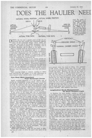
Imagine a vehicle with parallel-motion independent suspension to be taking a fast bend—a fairly common occurrence on long runs. It will at once be realized that, due to centrifugal force, the body and frame unit leans outwards from the centre of the curve and takes up a position relative to the ground similar to that shown in the diagram at the top of this page.
Because the wheels are constrained to move in a plane parallel with the web of the frame side-members, they, too, will lean away from the centre of the curve. The effect of this leaning is to force the wheel from its 'natural path into one induced by the steering mechanism. The point is clearly illustrated in the diagram.
Under right conditions, wheel and tyre form, in effect, the base of a cone. of which the apel is the centre of the
curve around which the wheel is rolling. For perfectly circular motion without wobble from side to side, when the cone is revolved, the base, obviously, must lean inwards towards the point. However, the tyre on the vehicle is made to lean outwards, so that its natural centre of rotation, the cone apex, is at a point where the centre line of the stub axle produced meets the ground, namely at P. Because the tyre must roll around a curve with its centre at 0, the distance which its inside face (A) must travel is less than that for its outside face (B), but the axis about which the tyre revolves is represented by a ,line passing through its centre and point P; therefore, the rolling radius of side B is less than that of side A and consequently side B should make more revolutions than A for the lobs distance travelled, with resultant tyre. scrub.
Longitudinal Scrub Measurement for Small Outward Angie.
To illustrate the point further, consider a vehicle to be travelling, around a bend at such a speed that the inside wheel is made to lean outwards at 2 degrees (a common achievement in private cars). Then, assuming the camber angle, the natural angle of the wheels to -Mae perpendicular, to be 2 degrees, as shown above, the off-side wheel will lean at about 6 degrees. The induced difference in radii of a tyre Nith a 20-in, rolling radius and a 6-in.-wide tread, is 0.63 in., and the difference in travel of the two sides over the length of tyre contact with the ground is 0.32 in.
If the scrub were lateral, that is, across the chassis, the flexibility of the rubber in the tyres would serve to damp it out by allowing the tyre shape to change, but it is, instead, longitudinal, or in the direction of the length of the vehicle, and any difference in motion of parts of the tread must take place against the scraping action of the road.
• Accordingly, with any vehicle having parallel-motion independent suspension and tyres of the above dimensions,' a particle of rubber on side B of the tread travels the whole length of the contact surface of the tyre and road while a particle on side A travels 0.32 in, less than this length, and the liar of rubber connecting them is distorted against the abrasive action or the road, thus causing wear.
When, independent suspension was first patented in 1905, Little was known about the necessary frame design for its inclusion in the chassis. For many years identical frames were used for both orthodox and independent suspension and, in consequence, the latter was a complete failure.
Forces set up by the wheels were tranamitted directly to the frame side-members and caused considerable distortion, steering geometry was upset and tyre wear was -excessive. It was not until the nineteen-thirties that the need for a special frame for independent suspension was realized; then, rigidity was improved and, unhappily, frame weight was increased.
The addition of weight to the private-car frame provides sufficient proof that its incorporation in commercial design will increase the weight there to a proportionately greater extent. If post-war legislation is to be based on the present system, the addition of any weight whatsoever could not be countenanced, as present light-weight vehicles are designed to the limit of material strength and any addition would plate them in the next-higher taxation 'class. For all vehicles, additional chassis weight means less pay-load.
It has been established that the theoretical centre about which the lateral roll of an automobile body takes place, in the case of vehicles with most types of independent suspension, is on the centre line of the chassis at ground level, whilst the same point, in the case of those using orthodox beam front axles, is also on the centre line of the chassis, but at the height of the wheel centres, the ideal position being at the height of the centre of gravity of the vehicle from the ground. • Thus, with most types of independent springing, rolling tendency is increased, a, • feature which is detrimental on the lightest car.
On a heavy lorry or double-deck bus, where roll is a recognized disadvantage, the introduction of a suspension system which would increase that fault would be a definitely retrograde step, and not only for roll reasons, but also for the added disadvantage that the tyre scrub previously described would be aggravated by the increase in the angle of the wheels to the vertical when kounditg a bend.
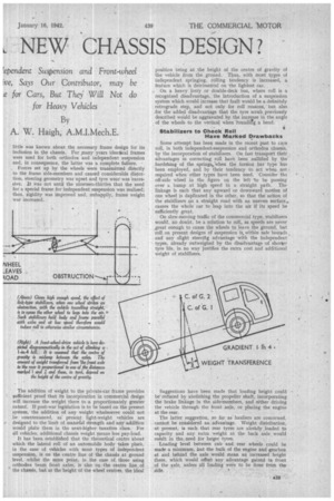
Stabilizers to Check Roll Have Marked Drawbacks Some attempt has been made in the recent past to cure roll, in both independent-suspension and orthodox chassis, by the incorporation of stabilizers. On fast transport their advantages in correcting roll have been nullified by the' hardening of the springs;when the torsion bar type has been employed, and by their tendency to act when not • required when other types have been used. Consider the off-side wheel in the figure on the left 'to bepassing over a bump at high speed in a straight path. The linkage is such that any upward or downward motion of one wheel is duplicated in the other, so that the action of the stabilizers on a straight road with an uneven surface,., causes the whole car to leap into the air if its speed be sufficiently great.
On slow-moving traffic of the commercial type, stabilizers would, no doubt, be a solution to roll, as speeds are never great enough to cause the wheels to leave the ground, but roll on present designs of suspension is. within safe bounds and any slight steeritg advantage with the independent types, already outweighed by the disadvantage-of shoraer tyre life, in no way justifies the extra cost and additional weight of stabilizers.
• Suggestions have been made that loading height could be' reduced by abolishing the propeller shaft, incorporating the brake linkagein the sideA:nembers, and either driving the vehicle through the front axle, or placing the engine at the rear.
The latter suggestion, so far as hauliers are concerned, cannot be considered an advantage. Weight distribution, at present, is such that rear tyres are already loaded to capacity and any extra weight at the back axle would result in the need for larger tyres.
Loading level between cab and rear wheels could be made a minimum, but the bulk of the engine and gearbox at and behind the axle would mean an increased height there, which would offset any advantage gained in front of the axle, unless all loading were to be done from the side. F7rther, the complications of controls, for instance, change-speed mechanism, besides increasing the chassis weight, would be an added disadvantage.
One type of vehicle which, possibly, would benefit from the rear-engine layout is the country service bus. A baggage platform could be incorporated over the engine and all passengers would enjoy the comfort of riding within the wheelbase. There would be no obstruction at the front end; thus providing an ideal arrangement for a oneman-operated vehicle.
Whilst front-wheel drive undoubtedly has a number of points in its favour, these are outweighed by the disadvantages of-the arrangement. It is generally agreed, on the one hand, that front-wheel skid, when cornering, is made less likely than with the orthodox layout, the steered wheels being driven and not pushed, as in the case of rear-wheel drive. On the other hand, however, if a condition be reached in which. the driven front wheels are on the point of spinning and not rolling, the skidding possibilities of the front end would be increased. Even -with conventional design, wheelspin on not abnormal surfaces is a common limiting factor.,
Low Loading Level an Advantage of Front-wheel Drive
As in the case of the rear-engined chassis, the loading height would be reduced to a minimum, both between the cab and the rear wheels and at the back end of the vehicle, the only obstruction to a perfectly flat platform being the whnel arches. If the back axle were placed right at the rear (so that no overhang were permissible with the vehicle dimensions complying with the legal overall-length require. ments) weight distribution would be greatly improved, the low floor level would obtain for almost the full body length and a minimum of obstruction would be offered by the wheel arches.
Engine, gearbox and front axle could be assembled in one unit and so mounted in the frame that, when overhaul or repairs became necessary to any of the major components, the complete assembly could be wheeled out of the chassis on the front wheels with little effort. From the service angle this feature of almost perfect accessibility of all important items is highly desirable.
Greater Unladen Weight and inferior Hill-climbing Unladen weight would, very likely, be increased and the relative complexity of the complete driving unit would add nothing to the desirable features of the chassis, but the biggest disadvantage of front-wheel drive is its poor hill-climbing capability.
On the previous page is sketched a vehicle incorporating the features previously pointed out, equipped with front. wheel drive and negotiating an incline of 1 in 4. Because of the new position of power and transmission units, it is assumed that the centre of gravity of the lorry is on a line perpendicular to the road and exactly between the two axles.
From this diagram it can be seen that weight transference due to the gradient, is towards the undrivea rear axle, thus relieving the front axle of some of its load.
In order that the vehicle may be able to clifnb the hill, the adhesion between the road and the driven tyres must be sufficient for a force uphill to be applied to the wheels, withobt their skidding, which is larger than that downhill resulting from the load and the rolling resistance of the vehicle.
This downhill. force is constant. for a given gradient, butthe weight on the.. front wheels, which governs the
amount of tractive effort which an be put through them without slip, is variable and dependent on the height of the centre of gravity from the ground as illustrated by the increased distance of weight transference for position marked C.G:2.
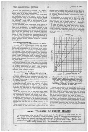
An examination of the accompanying graph shows that a double-decker, or any Vehicle with an 18-ft. 6-in, wheelbase, must have its centre of gravity within 4 ft. 1 in. of the ground if it is to climb a gradient of I in 4. The height of the centre of gravity for a 1 in 4.5 gradient is 8 ft. 6 ins, and above the actual position on a vehicle.
It might he argued from these results that if a lorry will climb a -hill of I in 4.5 it is up to its job, but the graph is compiled from figures giving only the best road conditions and does not take into account the possibilities of ice and snow, or even surfaces that become slippery when wet.
Whereas rear-wheel drive has something in hand to meet adverse conditions, the weight transference being towards the driven axle, front-wheel drive has little if any reserve and, when roads are icebound, would more than probably jib at trifling gradients. Even chains would be of little use in such circumstances, as the loading necessary to give them sufficient grip for hills would be absent.
The future may hold the secret of perfect suspension, but, until it is produced and the drawbacks of front-wheel drive and othet unorthodox chassis arrangements are overcome, the haulier will have to be content with improvements to individual components and carry on with the existing layout of his vehicle, which, after all, is giving him excellent service. •