


New Pressure-fluid Brake Servo
Page 25
If you've noticed an error in this article please click here to report it so we can fix it.
A'hydraulic servo device for power application of brakes has been developed by the Clayton Dewandre Co., Ltd., Titanic Works, Lincoln, well known in connection with vacuum-servo apparatus. It is notable for its ingenuity and it Should enable the brakes to be operated with ease and nicety, the driver's effort on the pedal being accurately reproduced in multiplied form.
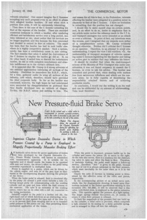
Power is supplied by a pump, which can be driven by the vehicle engine, and may be of the gear. type as illustrated in the accompanying diagram showing the principle of the device.
When the brake pedal is released, fluid is circulated idly by the pump (5) around a path which includes a tube (1) having escape ports (2) communicating with the working cylinder and an open end.,from which the fluid returns to the reservoir. The tube is an extension of the working piston, which has on its other side a rod (4) connected to the brake mechanism.
Suitably coupled to the pedal is a further rod (6), the right-hand end of which functions as an obstructing valve. It is enabled to abut against the open end of the tube (1) so as to prevent fluid from escaping and so as to transmit pedal pressure to the piston rod (4), thus permitting direct mechanical application of the brakes. When the pedal is depressed, pressure builds up in the cylinder and causes the piston (3) to move to the right. As the tube also moves, there is a tendency for the obstructing valve to open and allow the fluit to flow. Therefore, to maintain braking, the pedal must impart a follow-up motion. ,Excellent " feel " is given to the pedal, because the end of rod 6 is always subjected to the fluid pressure, which must inevitably be the same there as it is -in' the cylinder.
Clearly the ratio of increase ie braking power is determined E2y the effective areas of the valve and piston, respectively.
In the accompanying picture of an actual servo unit, which, like the diagrammatic drawing, is based upon illustrations included in the Patent specification relating to this invention (No. 541,233), it will be observed that a disc valve, -with fluted stem, is, employed in the piston extension tube. This operates against the pressure of ,a light spring. The larger spring—behind the = piston—is, of coarse, to return it when fluid pressure is released.
To limit The magnitude of the pressure that can build up in the cylinder, a relief valve is provided, which comprises a ball, retained on its seating by a flirty powerful spring, and is arranged to blow off into the reservoir.