


A SIMPLE FORM OF SERVO BRAKE.
Page 30
If you've noticed an error in this article please click here to report it so we can fix it.
A Résumé of Recently Published Patents.
COMMERCIAL motor vehicle design has always, in a most curions fashion, lagged behind that of touring cars, designers only adopting features which have long been used on cars and long after they have proved themselves to be perfectly satisfactory for that purpose. It is, therefore, only to be expected that a considerable time must still elapse before the " servo " brake, 'which. is now a frequent. Retro of the equipment of high-powered cars, at least amongst, those of Continental manufacture, begins to be regarded with any favour by commercial motor manufacturers, notwithstanding the fact that it would appear to be an admirable addition to the brake mechanism on, for ex
ample, a 30-seater motor coach, The time must, however, shortly come when this type of brake will have its due meed of attention in that connection, and for that reason we give a prominent place this week to an interesting invention by M. Paul Hallot, which is concerned with a simple form of this type of brake.
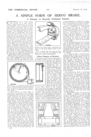
The essential point, about the construction, which is. described in this specification, No. 169,989, is that. the servo mechanism only operates when the speed
o the vehicle has passed a predetermined limit, a feature which Makes it particularly useful in connection with commercial vehicles.
A loose pulley, or extra drum, is mounted on the exterior of the ordinary brake drum, upon which it is, in normal circumstances, free to revolve. The cable which transmits the pedal or manual effort of the driver to the brake mechanism passes round this drum as round a guide pulley, and thus operates the brake or brakes in the orthodox manner.
Mounted in or about the brake drum, round which the loose pulley is located, is a weight, which is slung at. the outer end of a centrally pivoted lever. The lever is restrained by a spring, the tension of sdlich is readily adjustable, so that on a certain speed of revolution of the brake dnnn being passed, the weight flies out, and engages with a stop on the loose pulley, thus causing it to travel round with the main drum, taking the brake-operating cable with it, and very considerably increasing the braking effort This retards the car very quickly, but not so much as to skid the wheels, for, so soon as the predetermined speed is again passed (as the .car.slaws up), the lever, acting Under the influence of, the spring. returns to its inner position, and
B44 releases the brake pulley, depriving the brake of the extra effort whieh it provided.
It is claimed that this type of servo brake can with ease be applied to the mechanism of most existing cars.
Other -Patents of Interest.
The piston which has been patented by D. Napier arid Son, Ltd., and which is described in specification No. 189,719, is of the type in which a circumferential gapis formed between the head and body portions, which are, however, formed integral, being connected together by means of a truncate conical member, which has its largest diameter secured to the inner wall of the body, and its smallest diameter attached to the interior of the piston head, This provides for the heat of the head being conducted away to the bOdy, thence to the cylinder walls, and away, but makes no provision for regulating the expansion of the body in accordance with the expansion of the cylinder, Such provision is made in the design which is the subject of the patent. The skirt is slit longitudinally, and provided, at thejuriction between the inner wall of the skirt and truncated conical member; with a complete ring formed of
a metal which has a co-efficient of expansion Corresponding to that of the cylinder wall, a second ring may-also be used.
A novel arrangement of auxiliary road spring is described in specification No. 174,066, by Fabrics, di Melia e Aecessori .per Rotabili. The auxiliary. is shorter than the main .spring, both being, however, semi-elliptic, and is mounted above it, being fastened to it by the central . bolt, and shackled to it by swinging shackles, which are attached, to the ends of the auxiliary springs, hut swing under the main 'spring, so that. they only engage it when the load passes a certain limit.
F. W. Johnstone puts shackles at both 'ends of the front, springs, but restrains those at the front end by means of extra leaf springs, which are secured at one end to the frame, and at the other to an extension of the shackle. Their shape is such that they will also serve as buffers. His invention is described in specification No. 174,630.
A. L. King provides a remedy for the trouble which, he says, is experienced in oonnection with certain, makes of cars, in that they are difficult to start owing to the fact that the plates of the clutch stick together. He divides the propeller shaft and reunites the two portions by means of a sliding coupling,. which 38 controlled be a handle in the cab. For Starting, the joint is broken, and again made when the engine is running and the dutch has freed itself. The specification in which it is described is No. 189,612.
A two-speed gear; which, it is claimed, is of particular use in connection with the construction of warehouse trucks and similar vehicles, is described in Specification 'No. 173,217, by Etablissements Daudet et Dollen. It has the merit that the gears aye in constant mesh, but. involves the reversal of the rotation of the main driving shaft as the change of gear is effected. In one construction means for bringing this reversal about at. the Same time as the gear is changed is described. The underlying principle of the construction is the concurrent. movement of the gears on both the main and secondary shafts.
P. Shishkoff describes, in specification No. 189,532, a method of storing the energy of an engine in a rapidly rotating flywheel, and drawing on it as required. The engine is connected to the flywheel
through a clutch and gearing. When the speed of the flywheel reaches a certain predetermined limit the clutch is automatically disengaged. It is engaged again when. the speed has dropped below another limit. The following is quoted from the specification as an example of the use of this transmission :—" Assum
in„ct the engine to develop 20 and to take 30 minutes to run the flywheel up to speed, then the amount of energy stored in the flywheel is approximately 10 h.p.-hours. This energy is available for driving a, constant or variable load on the electric generator for a period of time varying with the magnitude of the
load. Considering two extreme cases, the flywheel would, for example, be capable of driving a load demanding onehalf horse-power per hour for, say,19 hours, or, alternatively, a load demanding 40 horsepower, for 15 minutes. . .'S