


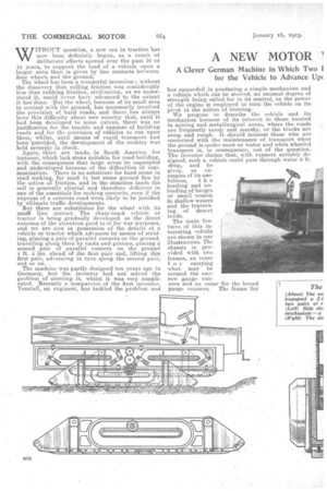
A NEW MOTOR
Page 18
Page 19
Page 20
If you've noticed an error in this article please click here to report it so we can fix it.
THAT STRIDES.
A Clever German Machine in Which Two for the Vehicle to Advance Up( lers are Placed on the Ground Alternately :h is Capable of Being Steered.
WITHOUT question, a new era in -traction has now been definitely begun, as a result of deliberate' efforts spread over the past 10 or 15 years, to support the load of a vehicle upon a larger area than is given by line contacts between four wheels and the ground.
The wheel has been a wonderful invention ; without the discovery that rolling friction was considerably less than rubbing friction, civilization, as we understand it, could never have advanced to the extent it has done But the wheel, because of its small area. in contact with the ground, has necessarily involved the provision of hard roads, and there has always been this difficulty about new eountry that, until it had been developed to some extent, there was no justification for the trouble and expense of building roads and for the nrovision of vehicles to rim Upon' them; whilst, until means of rapid transport had been 'provided, the development of the country was held severely in check.
Again, there are lands, in South America for instance, which lack stone suitable for road building, with the consequence that large areas lie unpeopled and undeveloped because. of the difficulties of communication. There is no substitute for hard stone in road making, for sand is but stone ground fine by the action of friction, and in the stoneless lands the soil is generally alluvial and therefore deficient in one of the essentials for making concrete, even if the expense of a concrete road were likely to be justified by ultimate traffic developments. But there are substitutes for the wheel with its small line contact. The chain-track vehicle or tractor is being gradually developed as the direct outcome of the attention paid to it for war purposes, and we are now in possession of the details of a vehicle or tractor which advances by means of striding, placing a pair of parallel runners on the ground, travelling along them by racks and pinions, placing a second pair of parallel runners on the ground
i 4 ft. 4 ns, ahead of the first pair and, lifting this first pair, advancing in turn along the second pair, and so on.
The machine was partly idesigned ten years ago in Germany, but the inventor had not solved the problem of steering it, whilst it was very complicated. Recently a compatriot of the first inventor, lienzlaff, an engineer, has tackled the probrem and has succeeded in producing a simple mechanism and a vehicle which can be steered, no unusual degree of strength being celled for in its control, as the power of the engine is employed to turn the vehicle on its pivot in the action of steering. We propose to describe the vehicle and its mechanism because of its interest to those located in mining and metallurgical areas, 'where the roads are frequently sandy and marshy, or the tracks are steep and rough. it should interest those who arc concerned with the maintenance of transport when the ground is under snow or water and when wheeled transport is, in consequence, out of the question.
fulness, i h e loading and unloading of barges or small vessels in shallow waters and the traversing of desert la lids.
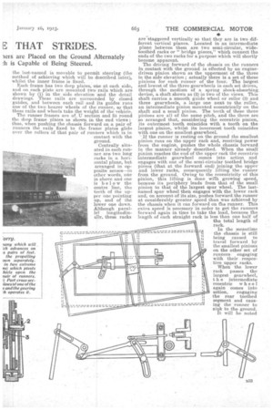
The main features of this interesting vehicle are shown in our illustrations. The chassis is provided with two frames, an inner 1 o r carrying what may he termed the narrow gauge runners and an outer for the broad gauge runners. The frame for the last-named is movable to peribit steering (the method of achieving which will be described later), whilst the inner frame is fixed.
• Each frame has two deep plates, one at each side, and on each plate are mounted two rails which are shown by (1) in the side elevation and the detail drawings. These rails are -surrounded by closed guides, and between each railand its guides runs one of the two bearer wheels of the runner, sp that these rails and wheels take the weight of the vehicle. The runner frames are of U section and fit round the deep frame plates as sho-wn in the end views: • thus, when pushing the chassis forward on a pair of runners the rails fixed to the, frame plates glide over the rollers Of that pair of runners which is in contact with the ground.
Centrally situated in each runner are two long racks in a horizontal plane, but arranged in opposite senses—m other words, one is above and one is below the centre line, the teeth of the upper one pointing up, and of the lower one down. Although parallel longitudinally. these racks are staggered vertically so that they are in two different vertical planes. Located in an intermediate plane between them are two semi-circular, widetoothed racks or "bridge pieces," which 'connect the ends of the two racks for a purpose which will shortly become apparent.
The driving forward of the chassis on the runners in contact with the ground is effected by an enginedriven pinion shown as the uppermost of the three in the side elevation ; actually there is a set of these pinions for each runner of the four. The largest and lowest of the three gearwheels in each set drives, through the medium of a spring ishock-absorbing device, a shaft shown as (2) in two of the views. This shaft carries a smooth guide wheel or roller (3) and three gearwheels, a large one next to the roller, an intermediate pinion mounted eccentrically on the shaft and a small pillion. The teeth of these three i pnions are all of the same pitch, and the three axe so arranged that, considering the eccentric pinion, its outermost tooth coincides with a tooth on the largest pinion, whilst its innermost tooth coincides with one on the smallest gearwheel.
' If the runner is resting on the ground the smallest pinion runs on the upper rack and, receiving power from the engine, pushes the whole chassis forward in the manner already described. When the snail pinion reaches the end of the upper rack the eccentric intermediate gearwheel comes into action and engages with one of the semi-circular toothed bridge pieces (that at the forward end) joining the upper and lower racks, consequently lifting the runner from the ground. Owing to the eccentricity of this this lifting is done with growing speed, because its periphery leads from that of the small pinion to that of the largest spur wheel. The lastnamed spur wheel then engages with the lower rack and, on account of its size, pushes forward the runner at considerably greater speed than was achieved by the chassis when it ran forward on the runner. This extra speed is necessary in order to get the runners forward again in time to take the load, because the length of each straight rack is less than one half of the total length of rack.
In the _meantime the chassis is still being caused to travel forward by the smallest pinions on the other set of runners engaging with their respective upper racks.
When the lower rack passes the largest gearwheel, t h e intermediate eccentric wheel again comes into action, engaging the rear toothed segment and causing the runner to sink to the ground. It will be noted
that the lifting and dropping of each runner occurs at the ends, so that, if provision were not made, the runner would he tilted or would he caused to jam. In order to avoid this, recourse is made to a very ingenious arrangement, consisting of a sliding rectangular frame and four bell-crank levers on each of the deep frame plates, two of the levers acting when the runner is being lifted and the other two whilst
it is being dropped. Each of these bell-crank levers is connected at one end to the compensating frame, whilst the other end is formed into a fork which will fit the ends of the axles of the bearer rollers carried by each runner.
Now, when the vehicle moves forward on a pair of runners the axles of the rollers are caught in the forks of the lower bell-crank levers. If the runners are now lifted by the eccentric spur wheels, the two lower bell-crank levers act as slide guides; in fact, their function is to enforce parallel motion, so that if one is moved the other, being connected to the same compensating frame, moves to the same degree and in the same sense. The lifted runners now advance along the upper portion of the rails and become disengaged with the lower bell-crank levers. The upper bell-crank levers act in a similar way whilst the runners; are being lowered, When the vehicle is travelling backward the levers act in the same way, but the procedure is reversed.
Each runner carries a series of blocks which are connected to the bottom of the runner by spiral springs so that they are capable of lifting to a small extent and thus compensate for small unevennesses, such as. atones, etc., in the road. Small rollers are also provided at each end in order to render easier the climbing of hills or the passage over obstructions, and to prevent the ends digging into the ground.
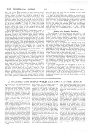
The vehicle may be likened to a horse running on four legs, each of which takes the form of a runner about three metres long. The outer runners are rigidly connected, as are the inner. At starting the vehicle rests on all four ; then it lifts the two outer runners, whilst the load rests on the narrow gauge pair. Then the outer runners are pushed forward for a distance of 1.3 metre and set down.The next moment the narrow gauge runners are lifted whilst the load rests an the ones in contact with the ground ; consequently, the vehicle strides
forward step by step, or can reverse in the same manner when required.
It will be seen that the vehicle is considerably different from the conventional type of tra-.`&-laying machine, as, in this case, it actually carries fixed rails and runs on rollers carried on a, suitable foundation, i.e., the runners which it plants on to the ground at each step. It is difficult to imagine a railway in which the wheels form. the permanent way and the rails are carried by the locomotive, but this is actually what occurs in this vehicle, except that the " permanent way " is only so for short periods.
Solving the Steering Froblern.
The problem of steering has been solved in a very simple manner. We have already referred to the fact that the 'narrow gauge frame is flied, and the broad gauge frame movable. Actually the large frame with its broad gauge runners may be turned round on a central pivot, the movement, of course, necessarily being limited.
The steering is controlled by a hand wheel from the driver's seat, but the actual steering is effected by power derived from. the engine, a small crank altering the p-sition of the large frame through the medium of bell-crank Ievev--. It is claimed that in this manner very narrow curves may be described., but improvements which are now being made will allow for turning on the vehicle's axis. The vehicle may be driven forward or backward at the same sp'eed, and owing to the method of steering may also be displaced sideways, as is sometimes necessary in hilly regions. We understand also that the length of stride. (1.3 metres) and the stroke of the runners (the latter being 300 mm.) may also be altered at the will of the driver while the vehicle is travelling. The.model illustrated hgs an engine of 24 b.h.p., and, with a loading space of eight sq. metres, has a capacity of five tons. The overall length is 6.6 metres, and the width. two metres. The speed is said to he between .eight and ten kilometres per hour, and gradients of 35 to 40 degrees can be climbed. It is claimed by the inventor that trailers of similar design can be used, and only the first vehicle requires an engine.