


Patents Completed.
Page 20
If you've noticed an error in this article please click here to report it so we can fix it.
TRANSMISSION GEAR. — Daimler Motoren. Gesellschaft.—No. 25,050, dated (under Convention), 8th November, 1205. —In accordance with this invention, the shaft (e) carrying the dynamo armature, or the like, is mounted in line with the top shaft (er of the speed-changing gear so as to permit of connecting them together by a clutch coupling (d, dl), the prolongation of the shaft (a) for this purpose being rendered possible by using a ring bearing (n, in) instead of a step bearing, as hitherto, for taking up the thrt-st of the friction cone coup'ing (k, The ring bearing is formed by a collar (a) arranged on the shaft (a), and bearing against the wall of the casing (tu), enclosing the change-speed gear, by the intermediary of an annular ball bearing (m). In order to permit of throwing the coupling di), between th.>, shafts (e, al. into gear, the sneed.changing gears (g, gi), which are mounted on the keyed shaft (a), are first moved into their middle position, so that the bottom shaft (M is completely disengaged, After slightly disengaging the friction cone (0) from the correspond ing member (k) by means of the coupling lever -(r), and against the amino of the spring (a) which bears against the sleeve (e). rigidly fixed to the shaft (a) by means of the pin (f), the clutch coupling (d, di) is thrown into gear ; this may easily be done as the shaft (a) and the members (k, hi) are not wholly disengaged, but are still rotating a little. Now the pump, dynamo, or the like shaft (c), may be engaged by throwing into full gear the friction coupling (k, hi), and, thus, the engagement of the shaft (e) is carried out without any stopping of the motor.
SPRING COTTER PIN.—Mulcahy.No. 5,272, dated 5th March, 1907.—The cotter pin (A) is of ordinary construction and is formed with a head (a). A circular spring (B) is attached to the head (a) of the cotter pin. This spring is made If flexible material which will easily bend so that the ends will extend downwards to either side of the pin (A). It will be
teen that the pin can be easily withdrawn without the aid of tools, and it is less Liable to become loose when subjected to shocks.
JOINTS FOR STEERING GEAR.— Birmingham Small Arms Co.—No. 3,596, dated 13th February, 1907.—According to this invention, an adjustable ball joint is mclosed within the hollow or tubular portion of one of the steering rods. The joint end of the steering rod (a) is arranged to receive a spherical trunnion (b) ind its bearing cups; a spring (rI-) is interposed between an abutment and the inner bearing cup. The outer cup is forced against the trunnion (b) by an adjustable screw (e). The sides (b1, b2) of the trunnion (b) extend through slots (0) formed in the sidcs of the tubular rod (a) and are embraced by the forked ends (11, fi) of the rod (f). A bolt (g) passes through the trunnion (I), and the forked ends (fl, f thereby connect the two rods (a, f) together.
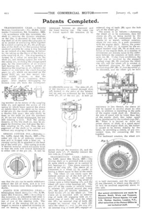
TRANSMISSION GEAR.—Jeffries.— No. 6,407, dated 16th March, 1907.—The driving shaft (a) is provided with a crank On upon which a. sleeve (d) is carried by hall bearings cL). This sleeve consists of part of the ring (d2). The sleeve (d) is connected to a wheel (f) by cranks (e) having a throw equal to that of the crank (b). The wheel (f) can rotate upon the reduced portion (g) of the huh (0) of a second wheel (e), which can rotate upon the driving shaft (a). The wheel (P rotates upon a roller bearing (p), and the wheel (gi) upon roller bearings (g3). The pins (el) of the cranks (e) revolve loosely in recesses (di) spaced around the ring (di); the pins (e2) revolve, similarly, in bored bosses (12) on the wheel (f). The s'eeve (d) is provided with an external ring of teeth (50) engaging with an internal ring of teeth (701 upon the wheel rim (hi); an external ring of teeth (38) engages an internal ring of teeth (Uzi) upon the wheel i) and, on the ring (dl, an internal ring of teeth (50*) engages an external ring of teeth (30) upon the hub (g1) of the wheel (0) The action is as follows :—Assuming the wheel (f) to be stationary, then the sleeve (d, di), on being moved by the crank (b), will be constrained -by the cranks (e) to travel, without rotation, about its own axis, in a path concentric with the engine shaft. Hence, the power sleeve, or shaft (3), is rotated by the engaged toothed rings (50, 70) at each revolution of the engine shaft, at a number of revolutions per minute equal to the difference between the numbers of teeth aforesaid, viz. 20. Under these conditions, the wheel rim (i) revolved by the engaged toothed rings (38, 58) overruns the wheel rim (32), and the wheel (g2) is rotated in a backward direction by the engaged toothed rings (50, 30). If, now the wheel (f) be liberated, and the wheel (e) be held stationary in lieu thereof, the sleeve (d) will be caused to revolve about its own axis, in addition to travelling in the path of the engine crank shaft (b). However, the rate of speed will be lower than that of the engine shaft, this latter speed being determined by the toothed rings (5P, 30). When it is desired to drive the power sleeve, or shaft, at a speed equal to that of the engine shaft (a), the farmer is caused to be driven directly by the latter, by providing a clutch, of any convenient type, for connecting the two together.
For backward rotation, the wheel rim
(fl is held stationary, and the wheels (f, g2) are liberated, in which case the sleeve (d) will be revolved negatively about its own axis.