


Injection Pump Acts as Governor
Page 58
If you've noticed an error in this article please click here to report it so we can fix it.
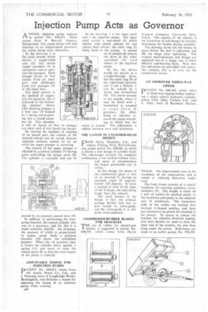
ANOVEL injection pump appears in patent No. 648,459. which comes from B. &send, Geneva. Switzerland. The pump shown will also function 'as an engine-speed governor, the action being quite automatic.
' In the drawing,, 1 is the main spindle Which carries a single-lobed cam (2); this moves tappet members (3) in succession, and so operates the plungers. Each plunger draws its fuel Supply from an inner purl and discharges from exit passages (4) in the usual way.
The chief novelty is the method of regulation for quantity; this is achieved in the followina • manner: Above each working plunger is a 'free one (5) backed by a spring and projecting into a closed chamber (6). This chamber :
is full of liquid, so that its plunger can enter only if this liquid can escape.
By varying the moment of opening of an escape port, the volume of the injected charge can be varied, because injection pressure cannot be set up while the upper plunger is retreating.
The Control of the upPer plunger is effected by a 'central cylinder (7) having ports controlling the escape ports (8). The cylinder is rotatable a'rid can be moved by an ex ernal control lever (9).
In addition to performing the foregoing function, the central cylinder also acts as a governor, and for this it is made vertically slidable. An oil-pump. the pressure of which is proportional to engine speed, feeds a pressure chamber (10) above the cylindrical, member. When the oil pressure' rises, it forces the cylinder down against a spring (II) and starts to close the release ports (8) so that the total output of the pump is reduced.
ADJUSTABLE TIMING FOR INJECTION rumps PATENT No. 649,221 tomes from the Austin Motor Co., Ltd., and J. Weaving, both of Longbridge Works, Birmingham, and discloses a means for adjusting the timing of an injection pump while running.
A40
In the drawing, 1 is the input shaft and 2 the injection pump. The input shaft carries a sun-wheel (3) which meshes with planet pinions (4) and rotates their carrier, the outer ring (5) being fixed to the casing. A second set of planets (6) returns the drive to the other sun-wheel (7) a n d thence to the injection pump.
So far, the device would act merely as a straight-through drive, but the outer ring (8) of the right-hand epicyclic unit is not a fixture; it can be rotated by a worm and wormwheel (9). The worm extends to the outside, where it may be fitted with a handwheel or coupled to some form of 'governor, " the effect being' to advance or retard the pump accord fog to which way the worm is turned. The adjustment is infinite 'between zero and maximum.
THE LATEST IN CYLINDER-HEAD DESIGN rROM Henry Meadows, Ltd., and " others, Fallings Park, Wolverhampton, comes patent No. 648,681, in which is shown a new design of cylinder head. The advantages 'claimed are complete combustion, a low surface-volume ratio, and space to accommodate the largest iiracticable size of valves.
In this design, the shape Of the combustion space is that of an inverted V, 'having an included angle of approximately 110 degrees. A valve is located in each of the sides of the V-shape, the inlet being larger than the exhaust..
The chief feature of the design is that the exhaust passage divides into two to pass round its valve-guide, and the valve-guide is at this point water-jacketed.
COMPRESSED-RUBBER BUSHES FOR SHACKLES
THE use of rubber for shackle-pin bushes is suggested in patent No. 648,547, which comes from Harris
Products Company, Cleveland, Ohio, U.S.A.. The essence of the scheme is the formation of end flanges by forcibly shortening the bushes during assembly.
The drawing shows (A) the bushes in place before the bolt is tightened, and (B) the shape after tightening. The original small-diameter end flanges are squeezed out to a larger size to form effective end-bearing faces. Note that the side-plates are provided with saucerlike recesses; this is to even out the compressive forces.
AN IMPROVED THREE-WAY TIPPER
DATENT No. 648,442, which refers I to three-way tipping bodies employing a single central hydraulic cylinder, comes from Alley Trailers, Ltd., and S. Alley, both of Burnham Market,
'Norfolk. The improvement rests in the sturdiness of the construction and is aimed at reducing distortion under load.
The body frame consists of a central backbone (I) carrying cantilever crossmembers (2). The weight is taken on a pair of arches (3) attached partly to the backbone and partly to the adjacent pair of cantilevers. The lowermost ends of the arches are formed into inverted U-shaped notches, and these seat themselves on pivots (4) attached to the chassis. To secure or release the notches, for selective direction tipping. pins (not shown) are used to close the open end of the notches, the pins then lying under the pivots. References are made to an earlier patent, No. 549,459.