


Patents Completed.
Page 36
If you've noticed an error in this article please click here to report it so we can fix it.
Complete specifications of the following patents will be sent to any address in the United Kingdom upon receipt of eightpence per copy at the Sale Branch, Patent Office, Holborn, W.C.
ADJUSTABLE SPANNER.—Terry.— No. 7,671, dated 29th March, 1910.—In this specification is described an adjust-able spanner, of the type which has a
number of movable packing pieces articulated to the jaw, so as to be capable of arrangement between or away from the Jaws. The invention lies in mounting the packing-piece pivot upon a part which is formed separately from the spanner itself, but which is subsequently attached. This enables the body of the spanner to be formed of sheet metal or to be forged instead of being cast. The weight of the finished article is thus considerably 'educed, and at the same time the strength is materially improved. A small bracket is formed, and in it is fixed a pivot which bears the articulated packing pieces. A spring is also inserted pressing on the latter so that they are held, in the position in which they are placed, by friction.
CONVERTING RECIPROCATING INTO ROTARY MOTION.—Lamplough. —No. 26,990, dated 12th January, 1910. —This mechanism is of the type in which a ring surrounds an inclined circular block fixed on a shaft, and in which the ring is provided with a pair of diametrically opposite conical rollers which fit within a tapered groove on the periphery of the inclined block. The object of the invention is to provide means for adjusting the conical rollers within the groove and to reduce the friction. A yoke is fitted on trunnions and is reciprocated by connecting rods on the working pistons ; in the yoke is fixed the outer member of a ball bearing which engages the axles of the conical rollers. This ball bearing is arranged with two rows of bearing balls, and a ball thrust in between them separated from the outer set of balls by a distance piece ; this distance piece permits the forward movement of the thrust bearing and allows the outer ball bearing to take up the wear of the conical roller in its groove. Suitable devices for locking the bearings and adjustments are described and illustrated. CARBURETTER.—Wolseley Tool and Motor Car Co., Remington and Pitt.— N. 5,4,31, dated 4th March, 1910.—The carburetter described in this specification is available for use with either petrol or paraffin. In the form illustrated, one float chamber is provided to which either kind of fuel is supplied by a suitable three-way valve. A jet is arranged horizontally at the aide of the float chamber, and the first air inlet is arranged so that the air passes vertically downwards across this jet, the mixture then passes into a sleeve valve. When petrol is being used, this valve, which is arranged horizontally, is moved to the extreme right position, the mixture then passes inside the valve and escapes by passages into the intake pipe. When this sleeve valve is moved to the extreme left position, it cuts off the direct communication of the inlet passage to the intake pipe, but opens an alternative path through a coiled pipe which is arranged to be heated conveniently in an enlarged portion of the exhaust pipe. The mixture passes through this spiral, and on emerging passes round the sleeve valve, and thence into the intake pipe. The engine is started up on petrol, and, when sufficiently warmed up. the sleeve valve is moved to the left position and paraffin substituted for petrol. The mixture is heated in passing through the spiral so as fully to vaporize the heavier fuel. The float chamber is provided with a drain cock at the bottom for draining off the paraffin when it is desired to restart the engine after running with paraffin, as, owing to the different specific gravities of tho liquids, it is necessary to remove the paraffin to allow the petrol to flow. An extra-air inlet is provided on the intake pipe. An alternative construction having two separate float chambers is also described and illustrated.
VENTILATION OF VEHICLES.— Owen.—No. 2,538, dated 27th July, 1910. —A device for ventilating vehicles as described in this specification consists of a tube passing through from one end of the vehicle to the other and communicating with the open air at each end. Inside this tube is a smaller one, having a space around it closed to the external air, but communicating by means of suitable holes with the interior of the vehicle. This internal tube is terminated at the rearward ends of the vehicle by an ejector nozzle lying in the larger tube. Owing to the movement of the vehicle, the air passing through this ejector withdraws the vitiated air from the interior of the vehicle. The particular feature of this construction is stated to be that there is no back or down draught inside the vehicle.
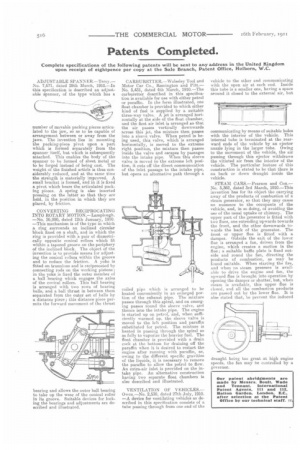
STEAM CARS.—Pearson and Cox.— No. 5,362, dated 3rd March, 1910.—This invention has for its object the carrying away of the products of combustion of a steam generator, so that they may cause no nuisance to the occupants of the vehicle, and, in so doing, of avoiding the use of the usual uptake or chimney. The upper part of the generator is fitted with two flues, one extending upwards towards the front, and the other downwards towards the back of the generator. The front or upper flue is fitted with a damper. Outside the exit of the lower flue is arranged a fan, driven from the engine, which creates a suction in the flue ; a suitable baffle plate is fixed outside and round the fan, directing the products of combustion, as may be found suitable. When starting the fire, and when no steam pressure is available to drive the engine and fan, the upward flue is brought into operation by opening the damper or shutter, but, when steam is available, this upper flue is closed, and all the combustion products are passed out by the lower fine. It is also stated that, to prevent the induced
draught being too great at, high engine speeds, the fan may be controlled by a governor.