


Commer Multi-pull Brake
Page 54
If you've noticed an error in this article please click here to report it so we can fix it.
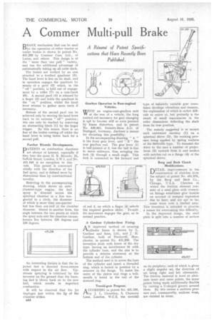
A R6ume of Patent Specifications that Have Recently Been Published. DRAKE mechanism that can be used 1-11for the operation of either tractor or trailer brakes is shown in patent No. 431,269 by Commer Cars, Ltd., of Luton, and others. This design is of the " more than one pull" variety, and has the additional advantage of automatically taking up all cable slack.
The brakes are worked by an arm attached to a toothed quadrant (3). The hand lever is free on its shaft, and in operation engages the quadrant by means of a pawl (5) which, in the " off" position, is held out of engagement by a roller (7) on a cam-track (6). A second pawl (4) is released by a finger (2) and holds the quadrant in the " on " position, whilst the hand lever returns to gather more teeth if necessary.
Release of the second pawl can be achieved only by moving the hand lever back to its extreme " off" position ; this can only be reached by removing an obstructing block (1) by the finger trigger. By this means there is no fear of the brakes coming off whilst the hand lever is being taken back for a second pull.
Further Ricardo Developments.
PATENTS on combustion chambers are always of interest, especially if they bear the name H. R. Ricardo, 21, Suffolk Street, London, S.W.1, and No. 431,345 is no exception to this
rule. This patent is concerned chiefly with the direction of the fuel spray, and is defined more by dimensions than by constructional novelty.
Referring to the accompanying drawing, which shows an antechamber-type engine, the fuel spray is directed across the spherical chamber in a line tangential to a circle, the diameter of which is more than one-quarter but less than one-half of the chamber diameter. Stated in another form, the angle between the two points at which the spray axis cuts the chamber circumference lies between 120 degrees and 150 degrees.
An interesting feature is that the injected fuel is directed down-stream
with respect to the air flow. Upstream spraying is criticized by the inventor on the ground that the burning fuel is blown back on to the new fuel, which results in imperfect combustion.
It will be observed that the jet impinges just within the lip of the chamber orifice.
B44 WITH an engine-cum-gearbox unit IN at the rear of a vehicle, the long control rod necessary for gear changing is apt to become stiff or even jammed by frame distortion, and in patent No. 430,951, Daimler-Benz A.G. of Stuttgart, Germany, discloses a means for obviating this possibility.
In the accompanying drawing, "A " is the front gear lever, and " B " the rear gearbox end. The gear lever (1) is ball-jointed at 2, but the ball is free to move sideways, thus swinging the fork (3) through a small angle. This fork is connected to the forward end
A Gardner Cylinder-liner Fixing.
AN improvedmethod of securing cylinder liners is shown by L. Gardner and Sons, Ltd., and J. H. Gardner, both of Patricroft, Manchester. in patent No. 431,238. The invention deals with liners of the dry type, "having an interference fit with the cylinder bore, and the aim is to provide a definite abutment at the bottom end of the cylinder.
The method used is to screw the bore of the cylinder and insert a threaded ring, which is locked in position by a setscrew in the flange. To assist the entry of the piston and rings a bellmouth is bored in the end of the screwed ring.
Toroid-gear Progress.
ACCORDING to patent No. 431,199. by J. L. Cloudsley, 5, Chancery Lane, London, W.C.2, the toroidal
type of infinitely variable gear sometimes develops vibrations and tremors, the explanation of which is rather difficult to arrive at, but probably is the result of small inaccuracies in the roller dimensions deflecting the shaft from its true position.
The remedy suggested is to mount each outermost raceway (1) on a spherical sleeve (3), the working pressure being applied by spring washers of the Belleville type. To transMit the drive to the race a number of projections (2) extends from it and meshes with notches cut on a flange (4) of the• spherical sleeve. • Borg and Beck Clutch Modifications.
DETAIL improvements in the construction of clutches form • the subject of patent No. 431,075, • by the Borg and Beck Co., Chicago, U.S.A. Clutches in which the friction element consists of a steel plate with riveted• on linings sometimes give trouble on account of unequal expansion due to heat, and are apt to become worn over a limited area. This invention is intended to provide a means for overcoming this difficulty. In the improved design, the steel plate is split into a number of sectors
on its periphery, each of which is given a slight angular set, the direction of set being right and left alternately. The friction material is fixed at alternate inner and outer points, the inner points being made additionally flexible by cutting a U-shaped groove around them. By this means a uniform pressure and, consequently, uniform wear, are claimed to occur.