


With Intent to Improve.
Page 20
If you've noticed an error in this article please click here to report it so we can fix it.
A Weekly Summary of Recent Patents, of Interest to the Maker and User of Commercial Motor Vehicles.
A Claude! Carburetter Insprove;.
• ment.
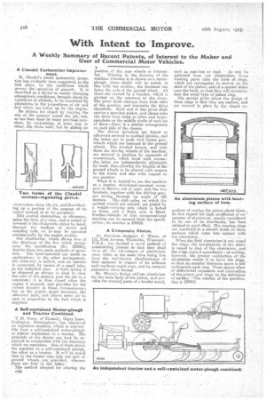
M. Clandel's latest carburetter invention has evidently been suggested, in the first place, by the conditions which gavern the operation of aircraft. It is described as a device to enable changing atmospheric conditions, brought about by variations of altitude, to be countered by alterations in the proportions of air and . fuel which are taken up by the engine. He attains his object by varying the size of the passage round the jets, not, as has been done on many previous occasions, by. contracting, in some way or other, the choke tube; but by sliding an
obstruction along the jet, and thus blocking up a portion of the passage atits centre 'instead of at its periphery.
This central obstruction, or obturator, takes the form of a•cone, and is raised or low eeecl in the choke-tube either by hand, through the medium of levers and coupling rods, -or it4 may he operated automatically by the. engine . se
Our illustration,. which :ShOwe two of the drawings of the five which accompany' the specification (No. 100251), depicts these two main methods of operation. Time hand-operated one needs no explanation; in the other arrangement, the obturator is hollow, and its interior is connected, by means of a smell tube,
the induction pipe. A light spring is so -disposed as always to tend to close the. area of the passage past the jet to a minimum; it is thus closed when the engine is stopped, and provides for the" richest mixture in thos.e circumstances ; but as the engine speed increases, the obturator falls, and allows more air to pass in. proportion to the fuel whieh is supplied.
A Self-contained Motor-plough and Tractor Combined.
'1'. G. Jones, of Thessaly, Gipsy Lane, Erdiegton, Birmingham, has conceived an ingenious machine, which is convertible from a self-contained motor-plciugh or similar implement to a tractor. The. principle of the device can best be explained in. conjunction with the drawings which we reproduce. One of thefts shows the machine as a' self-contained plough, the 'other as a tractor. It will be noted that in the former case only one pair of ground wheelsare provided, whereas there are four in the latter.
• The method adopted for altering the C62 position of the roar wheels is interest mg. Turning to the drawing of the machine whereon it is shown as a motor plough, three shafts will be noted, in -line with one another, the foremost one being the axle of the ground wheel. All three are carried by a bracket, which is pivoted on the rearmost 'of the threes
The pivot shaft emerges from both sides
of the gearbox, and transmits the drive therefrom. Each end of this pivot shaft carries a sprocket pinion, and chains take the drive from these to other and larger sprockets on the middle shafts of each set of three—there is a similar arrangement on each side of the chassis.
The driven sprockets are keyed or otherwise secured to toothed pinions, and the latter are in mesh with larger gear wheels which are fnstened•to the ground wheels. The pivoted frames, and with them the driving wheels' of the machine.
are secured in position by segments of wormwheels, which mesh with worms:
the latter are independently. adjustable by hand, thus allowing the heights of the ground wheels to be altered with, respect to the frame and also with respect to
one another. .
• When it is desired to use the machine as a tractor, thisShand-Operated wormgene is thrown ciiit of gear, and the two brackets, together with the driving gear, are swung through an angle of 180. degrees. • The stpb axles, on-whieh the •
ground wheels are carried, are joheed by a weight-carrying axle which is bolted to them, and a front axle is fitted. Further ?details of this unconventional machine can he secured from the specification; its number is 107625.
A Composite Piston.
An American -designer, C. Werra, of 111, East Avenue, Waukeeha, Wisconsin, U.S.A., has devised a novel methodof constructing pistons so that they shall have all the advantages of aluminittin ones, while at the same time being free from the well-known disadvantages of that material in respect of its softness and resultant rapid wear, and its unequal „expansion when heate,d.
Mr, Werra's design utilizes aluminium for the main body of the piston, and provides for wearing parts of a harder metal, such as east-iron or steel. As may be
gathered front our illustrationz these wearing parts take the form ot rings, which are rectangularin section on the skirt of the piston, and of a special shape near the head, so that they will accommodate the usual type of piston ring.
.The epecial point about the (resign of these rings is that they are endless, and are secured in place by the simple ex
pedient of casting the piston aboUt them., In this regard the high co-efficient of expansion of aluminium, usually considered to be one of its drawbacks, has been utilized to good effect. The. wearing rinks are maained to a smooth finish on thosesurfaces which come into contact With
• the aluminium. • .
When, the fluid aluminium is run round the rings, the tereperatare of the latter is raised to that of the aluminium, and the rings ,expand accordingly ; on cooling, however, the greater contractionofthe aluthieium *causes it to leave the rings, so that tut annular Clearance space_ is left underneath each ring. These Spaces allow of differential expansion end contraction of . the -piston andrings, .to the detriment of neither. 'The number of the specification is 107419.