


New Design for Coach Doors
Page 58
If you've noticed an error in this article please click here to report it so we can fix it.
BOTH hinged doors and those of the folding type have their disadvantages when fitted to a passenger service vehicle, and a new type of door, claimed to be an improvement, forms
the subject of patent No. 705,220 (Societa Riunite Trasporti Sorit," 6 Via Leon d'Ore, Parma, Italy).
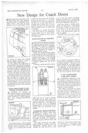
In this scheme, the single door is swung bodily to the side of its opening by means of a parallel-motion linkage, the pivots of which are mounted In the roof and in the floor. Referring to the drawing, 1 and 2 are the upper pivots, the lower ones being, of course, in line.
The door is shown in the open position by broken lines, and it will be seen that, although the movement approximates to that of a sliding door, the pivots give a far smoother action than would a slideway. Lever 3 and its link are duplicated at the bottom and form the means for actuation, either manually or by power.
CRACK PREVENTION IN OILENGINE CYLINDER HEADS rtA SCHEME for reducing the tendency towards the development of cracks in oil-engine cylinder heads is shown in patent No. 705,079 (DaimlerBenz A.G., Stuttgart-Untertiirkheim, Germany).
The drawing shows a typical cylinder head having a spherical pre-combustion chamber which discharges into the cylinder via a restricted orifice located A40 between the two valves, one of which is shown in broken line at 1. The area between the two valves, as indicated by the dots (2), is that most prone to cracking, and to prevent this it is proposed to shot-blast the area with steel balls, or similarly treat it by hammering or pressing.
The effect is to compact the surface of the metal and set up compressive stressea which will, to some extent, neutralize the expansive forces due to the temperature.
MANUFACTURE OF INJECTION PUMPS
A MULTI PLUNGER injection pump inpresents many problems in.maehining, quite apart from the fit of plunger and barrel. A scheme for simplifying the machining of the body is shown in patent No. 702,804, by E. Satzger. 17 Burgfried Hallein, Austria.
Usually the spring-retaining washers (1) are arranged to seat in counterbored recesses in the bores (2) which calls lot a special boring tool. In the proposed scheme, a flat underface (3) is milled along the length of the casing, forming a common seating face for all the washers.
To remove a spring assembly, a sharp edged fork ,can be forced in between the washer and the upper casing; this would be impossible if the washers were sunk in counterbores. The tappet bores and the upper ones are machined through holes in the bottom (4) of the casing; these are afterwards screw plugged AUTOMATIC BRAKE-ADJUSTER
PATENT No. 704,617 comes from Automotive Products Co., Ltd., Tachbrook Road, Leamington Spa, and shows an automatic adjusting device, the object of which is to maintain a constant clearance between shoes and drum.
The brake shown has two singleended hydraulic cylinders located at diametrically opposed points. The cylinders are each pivoted to a shoe as at 1 and each piston is similarly attached as shown at 2. Conventional pull-off springs are fitted and retract the shoes up to adjustable stop pins (3).
Each shoe carries a slidable pushmember (4) fitted with a Lard-wearing tip (5); this is initially set by the eccentric stop-pin to be just clear of the drum. A pin (6) on the shoe slides in a slot in the push-member when the brake is applied.
Mounted freely on the pin is a spiral cam (7) which is torsionally loaded by a spring (8) in a direction to increase its effective diameter. The cam is odd against slipping by a serrated engagement with end 9 of the push-member.
In operation, if the lost motion is -enough to disengage the serrations, the cam can turn and so set up a new zero for the return position of the shoes.
A NEW INDEPENDENT SUSPENSION SYSTEM
AN independent suspension system, claimed to give good riding over rough surfaces, is shown by I. Grenfell, South Road Works, Weybridge, Surrey, in patent No. 705,114. li is also claimed to be steadier when turning and not so inclined to cause skidding.
Each wheel is mounted on a transverse axle beam (1) which is pivoted to the frame at point 2, preferably in a rubber-bushed joint. The axle beam is constrained to move in an arc by the presence of an integral radius-rod (3) fixed to the beam and pivoted On to the frame at 4. The resilient members may be laminated or coil-springs; alternatively, pneumatic or rubber springs may be used.