


Torque Converter with Automatic Gearbox
Page 34
If you've noticed an error in this article please click here to report it so we can fix it.
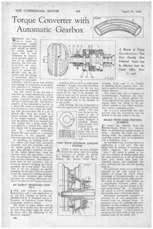
WWHILST the standard type of hydrodynamic torque converter operates fairly well within its limits, its torque range is small, and if wide variations be encountered recourse must be had to an additional gearbox. The two components are incorporatedin . a design shown in patent No. 551,251, with the difference that the change of mechanical ratio is 'arranged to occur automatically, without shock and without interruptiog the continuity of the drive. The patentee is F. Ileppner, 43,
ton Avenue, Leamington.
The unit shown in the drawing is described as being suitable for a :heavy vehicle. The output shaft (1) of the torque converter carries a sun-Wheel
(9) and a clutch disc (8). The 'reaction member of the converter is' carried on a sleeve 1`2) which is restricted to one way motion by a free wheel (3):Meshing with the. sun-wheel (9) is a Set of planets (0) ; these are carried on a clutch housing (6) which forms part of the output member. Meshing also with the planets (5) is an internal gear (10) formed into a brake drum, and controlled by a second free wheel (4). The clutch (8) is automatically operated -by centrifugal mechanism Behind the gear proper is a reversing Mechanism, of the epicyclic type, indicated generally by the figure 7.
In operation; at starting, :both the free wheels will resist their associated membera, and the Converter will -set the 'vehicle going via the mechanical gear; thus giving a reductiOn cif ratio. As the vehicle Speed brises", when the reaction wheel .(2) approaches a standstill, the automatic clutch engages and cuts out the reduction. This imposes a fresh load On the converter, and its' action is repeated, bringing the vehicle gradually up to top speed. The drum (10) is for the purpose of forcibly engaging the low gear when it is desired to use the engine for braking purposes.
The device -described also includes provision for ensuring additional cooling of the fluid in the torque converter.
AN EASILY PRODUCED LOCK
LOCK nuts continue to fascinate Lainventors, and a new application of an old idea features in patent No. 550,823 from E. A. Dennison and D. S. Kennedy, of Harewood Forest Works, Longparish, Andover, Hants.
The device is quite simple, but is open to the criticism that the nut will be more than finger tight for most of its travel after the beginning of the thread .is engaged.
A narrow slot is cut in a radial plane
forming a triangle with sides as follow: one is a radial line on the top face of the itut extending from the threaded centre to the edge of the chamfer; the next is, from top to,.bottom along the threads; the third is from the bottom of the tapped hole to the chamfer at a top corner.
After slotting, the nut is squeezed so that the upper part of the slot is partly closed. For nuts over l ins, in diameter a slot of standard hacksaw blade thickness is specified. Smaller nuts should . have thinner slots.
A meri,t of. the device lies in its adaptability to nuts of standard , type.
TYRE WITH INTERNAL COOLING SYSTEM
ATYRE in which air can .circulate around the inner. tube for cooling purp o a e s is shown in patent No. 550,892 by W. F. and D. C. Halsey, 147, Sutton Court Road,
London, "E.13, and C. C Gobell, '5, Barking Road; London; E.8. Airfeed is positive and the system appears highly efficient.
The inner tube has a number of circumferential V-grooves (2). interconoetted by a helical groove (1). When inflated in the cover, the grooves remain clear," but owing to the distortion caused as the wheel revolves, they create a pumping action.
'Air h.0 1 e conneEtingthe 'tube grooves with the atmosphere may be formed in the' tyre walls or the rim.
BRAKE WITH CONE FRICTION ELEMENT .
INpatent No. 550.557, lrom the Kelsey-Hayes Wheel Co., Detroit, Mich., is described an unusual design of brake. Suitable for both free and driving axles; the scheme employs a revolving Coaical shoe in co-operation with a stationary drum.
, An accompanying drawing shows an application to a live axle. The hub flange (10), in addition to carrying the wheel, supports the cone-shaped " shoe "(8) which is pulled to the hub by a number of spring-loaded pins (9) and centred by a, set of screwed studs (11); which also form the adjusting means, and constitute the drive between the hub and the moving element.
The stationary drum (1) is resiliently attached to the axle casing by a number of straps' (5) which whilst anchoring it circumferentially at the same time permit limited axial motion. The drum is brought into contact by a ring-shaped hydraulic piston (2), which works in a ,groove turned in the axle-casing flange (6). A connection (3) serves to convey pressure fluid to the annular space behind the piston.
Alternative mechanical operation is provided for by cam mechanisms (4) worked 'from an external lever. A spring-on cover (7) performs the dual function of. dirt-exclusion and retraction, though additional springs may be used for the latter, A servo action is created as the shoe tends to ride up the rounded ends of the studs (11).