


Interesting Injection System
Page 92
If you've noticed an error in this article please click here to report it so we can fix it.
PATENT No. 870.383 shows an injection pump in which the main plunger is cam-driven but the actual injection is performed by a second plunger,
hydraulically coupled to the first. (P. Bessiere, 55 Boulevard du Commandant Charcot, Neuilly-sur-Seine, France.) In the drawing the main cam-operated plunger is shown at 1. This draws in fuel from the Port (2) and, on the upstroke, discharges it via a ball-valve (3) into a cylindrical space (4).
This contains a free plunger (5) loaded by a spring. When forced up by the pressure under it, the plunger delivers the • EXHAUST PIPE COOLING
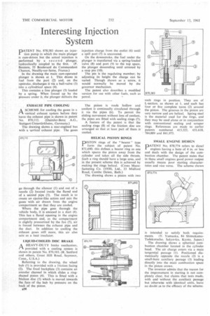
A SCHEME for cooling the gases in a I—I vertical exhaust system before they leave the exhaust pipe is shown in patent No. 870,112. (Daimler-Benz A.G., Stuttgart-Untertiirkheim, Germany.)
The drawing shows a rear-engined bus with a vArtical exhaust pipe. The gases go through the silencer (1) and out of a nozzle (2) located inside the flared end of a second pipe (3). The result is to create an ejector-like action and mix the gases with air drawn from the engine compartment so that they are cooled.
Where the pipe goes through the vehicle body, it is encased in a duct (4). This has a flared opening in the engine compartment and, as the compartment is slightly pressurized by the fan (5), air is forced between the exhaust pipe and the duct. In addition to cooling the exhaust gases still more, this air also actsas a heat insulator.
LIQUID-COOLED DISC BRAKE
.1-1 A HEAVY-DUTY brake mechanism,
provided with a cooling system is shown in patent No. 870,103. (R. Sanford and others, Great Hill Road, Seymour, Conn., U.S.A.) Referring to the drawing. the wheel hub (1) is provided with a friction facing (2). The fixed backplate (3) contains an annular channel in which slides a ringshaped piston (4). This is fitted with a friction disc (5) which is moved towards the face,Of the hub by pressure on the back of the piston.
n5R injection charge from the outlet (6) until a spill port (7) is uncovered.
On the downstroke. the fuel under the plunger is transferred via a spring-loaded valve (8) and port (9) to the top space, the plunger descending until arrested by a stop pin (10).
The pin is the regulating member; by adjusting its height the charge can be varied. Though shown as a screw, it would normally be moved by the governor mechanism.
The patent also describes a modified version for use with other fuels, such as • petrol.
The piston is made hollow and coolant is continually circulated through it via the pipes (6). To permit the sliding movement without loss of coolant, the pipes are fitted with sealing rings (7).
A feature of the patent is that the sealing rings (8) of the friction disc are arranged so that at least_ part of them is ' cooled.
HELICAL PISTON RINGS
DISTON rings of the "bearer" type
form the subject of patent No. 871.690; this defines a bearer ring as one which spaces the piston away from the cylinder and takes all the side thrusts. Such a ring should have a large area, and in the present scheme this is achieved by making the rings helical. (Cross Manufacturing Co. (1938), Ltd.. 33 Midford Road, Combe Down, Bath.) The drawing shows a piston with two such rings in position. They are of L-section, as shown at 1, and each has four or five complete turns (2) around the piston. The grooves in the piston are very narrow and are helical. Spring steel is the material used for the rings, and they may be used alone or in conjunction with conventional sealing and scraper rings. References are made to earlier patents numbered 415,322. 651.618, • 784.889 and 841,975.
SMALL ENGINE DESIGN
PATENT No. 870,774 refers to diesel engines having a bore of 4 in. or Tess and deals with the design of the combustion chamber. The patent states that in these small engines good power output usually means poor starting characteristics and vice versa. The scheme shown
is intended to satisfy both require
ments. (Y. Yarnaoka, 84 ShimokamoTadekuracho. Sakyo-lcu, Kyoto, Japan.)
The drawing shows a spherical combustion chamber located in the cylinder head. The air charge enters via a main tangential passage (I). Positioned diametrically opposite the nozzle (2) is a small-bore auxiliary passage (3) leading directly into the main combustion space in the piston crown.
The inventor admits that the reason for the improvement in starting is not completely clear, but claims that tests made, With and without the auxiliary passage but Otherwise with identical units, leave no doubt as to the efficacy of the scheme.