


AN IMPROVED CARBURETTER.
Page 30
If you've noticed an error in this article please click here to report it so we can fix it.
A Resume of Recently Published Patent Specifications.
THE Stewart-Warner Speedometer Corporation of America, in specification No. 237,936, show a carburetter for which it is claimed that the richness of mixture will be suitably varied for all conditions of operation of the engine under varying loads and speeds, from idling to high speed under full load.
So many alleged improvements in carburetters have been patented lately that it is refreshing to find one that seems on the face of it to have some features which suggest novelty and usefulness, and we shall watch with interest the development of this invention.
The construction of this carburetter is very simple. The float is of the usual American type, and the throttle is of the butterfly type, as shown in the diagram. Two Venturi tubes or contractions are provided, one larger than the other. The larger one is that which the air meets first, and, after passing through it, the air has to go through the smaller one. It will be seen that the nozzles are not placed in exactly the same relation to the smallest part of the contractions or Venturies. It is well understood that at starting of the engine, and when idling, a richer mixture is desirable than when running at high speed or under load.
It is known that it is possible to increase the speed of an air flow through a Venturi to a stage whichis beyond its capacity to respond in giving a proportionate supply of fuel to air. The object of the two differently proportioned Venturies is that, should the air now bel raised beyond the capacity of one of the Venturies to Produce an increase of fuel flow proportionate to an increase in air velocity, the stage of responsiveness of the other is reached, and, by lap allowingesdoemclei noeveorf
responsiveness of the first and growth of responsiveness of the second, the maintenance of proper proportions of air and fuel will be automatically effected throughout a wide range of engine speeds and throttle openings.
An Indicator for Showing the Temperature of the Cooling Water. A DEVICE for indicating and regulating the temperature
of the water in the circulating pipes is shown in specification No. 224,234 by Jean.Georges Dintilhac, of France. In this specification it is pointed out that fuels of different volatility work best, each at its own particular temperature. With this object in view the inventor has provided a pipe leading up to the dash, or some other place within the view of the driver, which is fitted with a thermometer, so that the temperature of the water can be seen at all times. Further than this, he provides a valve or tap in the pipe leading to the engine from the radiator, which is operated by means of a Bowden wire or other convenient means, whereby the flew of water can be either checked or stopped at the will of the driver. The specification suggests that this device may be used with or without a thermostat, so that the fuel being used at the time may have the benefit of the most suitable temperature.,
Improvements in Friction Clutches.
TEM Brown-Lipe Gear Co. of America, in their specifica-, tion No. 238,107, describe what they claim to be an improvement in the detail construction of friction clutches. Although shown applied to a single plate clutch, the invention is equally applicable to multi-plate clutches. In a somewhat lengthy specification they point out the difficulty of machining all-the parts of a plate clutch, where it is essential that the mating surfaces 'contact with each other accurately (146 —so perfectly that there are no appreciable errors. It is also pointed out that it is, not easy to maintain a clutch in such a condition that all surfaces meet correctly, owing to spring of shafts, etc. In the present case the general construction is of the ordinary type, the flywheel being indicated in our diagram by dotted lines, whilst the bearing carrying the shaft farthest from the engine and the withdrawal mechanisim are all of common type. The spring bears, at its right-hand end, against a bail bearing, which is anchored, in so far that it cannot slide away, whilst the left end of the spring bears against a sliding member which actuates the levers.
It will be seen that the main' member is not made integral with its long sleeve boss, but the latter is con-. structed with a head provided with a spherical face, which engages the main sliding member and allows it to take up a true position with relation to the other members of the clutch, even" if errors due to inaccurate machining or spring of shafts be present.
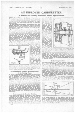
Brake Compensation.
-1-15 STEVENSON and G.W.K., Ltd., describe in their speci
fication No. 238,062 a simple device for compensating the brakes on all four wheels by means of one lever. As will be seen from the illustration, a lever (A) is pivoted to one side of the frame and is free to move in a horizontal plane on the other side member.
Attached to this lever (A) by means of a pivot is a second member (B). Attached to B are two pulleys which carry cables passing to the brakes to be operated. The brakeoperating pull-rod is centrally situated, and acts to pull A in a forward direction; this carries the pivot on which It is mounted forward and, consequently, puts a tension on both cables simultaneously. The lever (B) turns On a point situated near its centre, and, although free to find its own centre of movement to an extent, is provided with a safety device in the form of a slotted Member anchored to the frame by the rods shown and a pin which engages in it. The object of this slot is to prevent a total failure of the brakes should one of the cables break, in which case both brakes would become useless were it not for the slot limiting the movement of B about its centre. See-saw levers are mentioned as being used in some cases instead of pulleys and cables.