


A Two-speed Axle For Light Vehicles
Page 54
If you've noticed an error in this article please click here to report it so we can fix it.
A Resume of Recently Published Patent Specifications
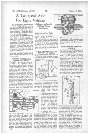
THE Timken-Detroit Axle Company, Detroit, Michigan, U.S.A., is a concern specializing in the production of two-speed axles, but, hitherto, they have been intended mainly for the heavier types of vehicle. Patent No. 602,623 shows a lighter unit suitable for vehicles in the 10-cwt.-50-cwt. classes.
In the main, the design follows the usual practice of this concern. A crown-wheel (1) drives a cross-shaft (2) upon which is journalled spur pinions of different size (3 and 4). A clutching arrangement (5) enables one or the other of the pinions to drive the differential-cage, which is fitted with spur gears (6). The interior construction of the differential and the axle shafts is
• substantially conventional, and calls for no special comment. • The crown-wheel and pinion are of the hypoid type, which means that the pinion can he located above the axis of the cross-shaft.
GEARBOX INCORPORATES DIFFERENTIAL ACTION 11DATENT No. 602,319, from H.
Hobbs, 28, Woodcote Road, Leamington Spa, discloses improvements in transmission systems for road vehicles. Referring to the drawing, the engine input shaft (1) carries a rotary housing containing two friction clutches (2 and 3). These are operated hydraulically by flexible diaphragms, which are rnergized by the admission of fluid under pressure to either or both. A feature of the scheme is that oil is permitted to reach the friction faces, to prevent harsh engagement as the oil has first to he squeezed out.
The left-hand clutch drives a planetspider (4). the sun-wheel bevels of which are mounted one on each of a pair of concentric shafts (5). The inner solid
me can be dog-clutched to the main 3utput shaft (6) of the gearbox. The xiter shaft carries a pinion (7), which Irives the layshaft (8) of the gearbox. The result is that the output shaft and the layshaft are driven by a differential after the manner of the road wheels of a car. The right-hand clutch drives only the outer tubular shaft, and when both clutches are engaged, the differential is locked and a straight-through drive is A36 transmitted. By suitable selective clutching and sliding of the gearbox pinions, five forward ratios, a reverse and a neutral can be obtained.
The specification gives full details of the hydraulic control gear and the synchronizing arrangements. An outstanding feature of the action is that owing to the division of the drive by the differential, changes in ratio can be made with little or no interruption in the transmission of power.
UNUSUAL METHOD OF WATERPROOFING AN ENGINE
AROAD-VEH1CLE engine that will function when immersed in water, is shown in patent No. 602,568, which
comes from Willys-Overland Motors Incorporated, Toledo, Ohio, U.S.A. No doubt originally intended for military purposes, the scheme should, nevertheless, be of considerable value for vehicles which have to operate over roadless country.
The primary requirement is. of course, that piping, at a high level, be used for the inlet and exhaust; these are shown at 1 in the drawing. The ignition system must also be kept completely dry, but this is not difficult to arrange. The main feature is that water must be prevented from entering the crankcase, and the patent describes an effective method of achieving this.
Some of the exhaust gas is diverted into the crankcase. In this way sufficient pressure is built up inside to resist the inflow of water. So that the exhaust can be given sufficient backpressure, an obstruction is placed in the exhaust pipe, taking the form of a weighted piston housed in the end (2). A suitable value for the back-pressure is from 3 to 7 lb. per sq. in., and this can be maintained without utscluly affecting the performance of the engine. Before the exhaust gas actually reaches the crankcase, it is first passed through a condensing chamber (3) to remove the water-vapour formed during combustion.
MECHANISM FOR EMPTYING DUSTBINS
AN attachment for the loading-end of a refuse-collecting vehicle, is shown in patent No. 602,569, by A. FrazerNash, 84, Kingston Hill, Kingston, Surrey. In this scheme the loading aperture in the body is closed at all times except when a bin is actually being emptied.
The drawing shows the mechanism as built on to the rear of a vehicle. The loaded bin is placed on a movable frame fitted with a hook-like member (1) at the bottom, and a pair of spring
catches (2) to hold the handles. The frame runs in guides and can be lifted by rods terminating in chains which surround stationary eccentric sprockets (3). When the lifting motion is forcibly arrested, these sprockets create a turning moment which tips the bin. The rods are lifted by arms (4) pivoted about bearings (5) and powered by an hydraulic ram, not shown. The power comes from a pump driven by the batteries on the vehicle.
. A flap (6) normally covers the body aperture, so that no dust can blow about, but it can be pushed open by the entry of a tipping bin. When the bin is fully inside the body, it is arrested by resilient stops (7); these vibrate slightly when struck and so impart a shaking motion to the bin to assist its discharge. This motion is increased by the provision of springs (8) on the rods.