


Trailer Brake with Adjustment for Load
Page 36
If you've noticed an error in this article please click here to report it so we can fix it.
A Resume' of Patent Specifications That Have Recently Been Published .
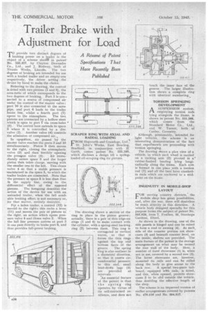
MO provide two distinct degrees of
braking power on a trailer is the object of a scheme shown in patent' No. 555,417, by Clayton Dewandre Co., Ltd., and J. Rodway, -both of Titanic Works, Lincoln. The two degrees of braking .are intended for use with .a loaded trailer and an empty one respectively, the driver setting . the device by hand to make the choice.
Referring to the draWing, the control is fitted with two pistons (1 and 9), the area-ratio of which corresponds to the two degrees of braking. Port 3 is con-.• nected to a source of compressed air under the control of the master valve ; port 10 is also -connected to the same pipe, and port 6 leads to the trailer brake line, whilst a fourth port (7) opens to the atmosphere. The two pistons are connected by a hollow stem which is open to port 7 via cross-holes (8). The central bore extends to space 5 where it is controlled by a disc valve (2). Another valve (4)-controls the admission of compressed air..
In opeisttion, air passed bY the master valve reaches the ports 3 and 10 simultaneously. Piston 9 then moves to the right, closing the atmospheric valve (2) and .then forcibly opening
the press,ure valve (4). Air immediately enters space 5 and the larger piston then takes charge, moving with the smaller one.to the left. This closes valve 4 so that a stable pressure is -maintained in the space 5, to which the trailer brakes are connected. Note that the pressure in space 5 is less than -that in the supply line, owing to the differential effect of the opposed
pistons The foregoing describes the action of the device for use with an. unloaded trailer, when the full available braking effort is not necessary or, for that matter, entirely desirable.
For a laden trailer, a Control (12) is moved to the right.; this rocks a lever. (11) and moves the pair of pistons to the right, an action which opens pressure valve 4 and Closes valve 2. -When the full line pressure arrives at port 3 it can pass directly to brake port 6, and thus provides full-power braking.
SCRAPER RING 'WITH AXIAL AND RADIAL LOADING
FROM Hepworth and Grandage, Ltd., St. John's Works, East Bowling, Bradford, in conjuncion with H. Garth, comes patent No. 555,348, which discloses a design Wr a spring. loaded oil-scraping ring for pistons.
The drawing shows a. section of the ring in place in the piston groove; actually, there is a pair of thin edge-on rings (1 and 4) to make contact with the cylinder, with a spring-steel backing. ring (2) between them. This ring is
-corrugated in vertical_ waves, so that it forces the thin rings against the top and bottom faces of the groove. • The spring 'ring is also resilient in a. diametral direction, so that it exerts circumferential pressure: to this end, small bent-dovtn lags (3) are provided at intervals.
'An essential feature of the patent is that the spring ring operates by virtue of its sell-contained resilience, and does not touch the inner face of the groove. The larger illustration shows a complete ring with identical numbering..
TORSION SPRINGING DEVELOPMENT
ASUSPENSION system, employing torsion rods lying alongside the Hanle, is shown in 'patent No. 555,388, which comes from the Standard Motor Co., Ltd., and W. Turner, both of
Canley, Coventry, Although, presumably, intended for light vehicles, the scheme is an interesting demonstration of the fact that experiments are proceeding with torsion. springing.
The drawing shows a plan view Of a vehicle, in which each wheel is carried on a rocking arm (2) pivoted in a' 'robber-bushed • bearing lying longitudinally along the frame. Each arm is 'formed in one piece with a torsion sod (1). and all the bars have crankedin ends which are anchored to a midpoint on the frame.
INGENUITY IN MOBILE-SHOP LAYOUT
FOR. serving country districts, the mobile shop has great possibilities, and, after the war, there will doubtless be much a.ctivity in this direction. A vehicle body deSigned specially for this purpose forms the subject of patent No. 555,028, from T. Foulkes, 35, Stanhope Gardens, Ilford.
As shown in the drawing, one of the side panels is hinged and can beraised to form a roof or awning (9). Al each side of the counter portion are showcases (3) and beneath counter level, on the inside, shelvesare provided. The main feature of the patent is the storage arrangement on what may be termed the rear wall of the body. Here, a number of fixed showcases (I) is, when not in use, covered by a second row (2). The latter showcases . are, however, mounted On rails and can be rolled along the body to give access to the hack row. A special' two-piece tailboard, equipped with _rails, is fitted, and this, when opened, permits showcases 2 to be slid 'outsidethe vehicle, thus doubling the effective length of the shop.
The scheme is an impzoved version of earlier arrangemenits covered by patents No. 410,516 and No. 554,51.7.