


Patents Completed.
Page 30
If you've noticed an error in this article please click here to report it so we can fix it.
CARBURETTER.--No. 9,209, dated under Convention let January, 1908—Socie'tt et G. Longuemare Freres.-This invention relates to a carburetter, in which the air and fuel valves are operated by one control mechanism. The usual casing (1.1 is divided, by an annular partition (5i, into the upper and lower chambers (4, 3). Within the lower chamber 13) is arranged the usual spraying nozzle (21, and surrounding this nozzle is a tube (6) supported by the partition (5). Each of the chambers (3, 4) is provided with an opening (8, 9) in which are arranged butterfly valves (10, 11) respectively. These valves are carried by a spindle (12), common to both, which extends beyond the top of the casing and carries a lever (13), to which is pivoted a connecting rod (14). The rod (H) is provided with an extension (15), which is suitably bent so as to allow a journal (16), carried by one arm of a double-arm lever (17), to slide thereon. Interposed between a not, carried by the extension (15), and the journal (16) is a spiral spring (24). The lever (17) is rigidly secured to a spindle (18), which is arranged concentrically within the c.arhuretting chamber t41, and is supported by a perforated disc (19), which, in turn, is connected to a ring (21! having recesses (22) arranged diametrically opposite ; recesses (23) are also pro. \tided in the partition (Si. The opening (9) in the carburetting chamber (4! is connected to the induction pipe of the engine, and the opening (8) in the chamber (3) constitutes the main air inlet. It will Lie seen that with the parts in the position as shown in Figure 2, when the lever (17) is moved to the left by any suitable gear the valves (10, 111 will be opened, and fur. ther movement of the lever in the same direction will catse the recesses t) in the ring ((21) to register with the recesses (23) in the partition (5), as shown in Figure 4, thereby allowing air to pass direct front the chamber (3) to the carburetting chamber (4) ; by this means the strength of the mixture in the carburetling chamber (l) can effectually be regulated.
LUBRICATOR. -Daimler Motoren Gesellschaft.—No. 20,298-07, dated, under Convention, 12th September, 1906.—This lubricator comprises a receptacle (e) for the lubricant, in which is arranged a crankshaft (a) for actuating the pumps (di. The pumps (d) draw lubricant from the receptacle (e) through the pipe (f) and force it through the channels (h, 111, h2) to the parts which are to he lubricated. The two pumps (d) are governed by means of a rotary valve (I) which is common to both, and which is driven by the shaft (a), through reducing gear, at half the speed of the said shaft (a). The rotary valve (i) consists of two cones which are held together by means of a spring (k). The operation of the device is as follows : for each revolution of the valve (it, the shaft (a) makes two revolutions. The pump (di during its suction stroke is continually in communication with a groove (t), which is so arranged that it establishes communication between the port
(ri and the passage (/). During the tion stroke of the pump, the valve tii makes a quarter of a revolution, so as to close the port (r) by means of the stop
(ii. The stop (21) then comes opposite the opening leading to the pipe outlets: (h2, hl, and hi, so that oil is forced in turn through these openings. It will be s.-.'en that, during the motion of the groove part (t) over the outlets (h2, hl, and h' , there are intcryals when the groove (g) will be entirely closed. During these intervals, the pressure of the oil in the pump caust:s the valve parts (i) to be pressed outwards and some of the oil finds its way between the valves (i) and the casing (g(.
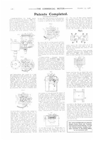
ROLLER BEARINGS FOR CRANKSHAFTS.—Batem.an.—No.2_9,352, dated 10th October, 1907.—This invention relates to roller bearings for connecting-rod
heads, and has for its object the provi sion of small overall dimensions ant simple construction, which will enable tb. device, if necessary, to be employed et a multi-cylinder engine crankshaft. Th. hearings consist of a split bush (E) having flanged inturned edges whid form pockets for retaining the ml lers. This bush is prevented from rotat ing on the crankshaft by means of pin (D, D1), which engage holes in the busl (E) and in the crankshaft (A). Holes an provided ii the flanges of the bush (E into which the rollers (B) alternately ei tend at each side, so that they are suitabl spaced. The rollers (13) are inserted alte: nately through the boles in the out flanges, one end of the rollers fitting i the hole of the outer flange, and the oth.< end resting in the pocket of the opposit flange. The rollers take bearing on tt track faces of the hardened collar (E) an the hardened faces of the connecting-re end and its cap.