


Adjustable Towing Ball Joint
Page 42
If you've noticed an error in this article please click here to report it so we can fix it.
'TO eliminate rattle due to wear is the I object of a refinement in tractortrailer couplings shown in Patent No. 526,705, by A. Dear and J. Brockhouse and Co., Ltd., Victoria Works, West Bromwich.
The scheme applies to the ball-andcup attachment used by the above. concern, and deals with an adjustable member to compensate for wear. In the drawing, the ball (3), carried by the tractor, is enveloped by a hemispherical cup (4) and locked by a below-centre nose (2) on the releasable handle. This handle pivots on a bolt (1) and the patent covers the use of an eccentric porti6m on the bolt. The handle is pivoted on the eccentric part and, by turning the bolt-head, it is possible to effect the adjustment required to tighten the ball.
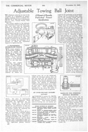
A PROGRESSIVE SWASH-PLATE ENGINE
THE latest progress in. swash-plate engines is shown in patent No. 526,384 by L. Istad, 115, West Roselle Avenue, Roselle Park, New jersey, U.S.A. The design abounds in novel features, which we can only summarize.
Having two angular throws the crankshaft is carried in three bearings, two outers and a centre one. A journalled wobbledisc (8) is carried at each end, and restrained from rotation by means not shown. Six Six pairs of horizontally opposed pistons are employed. Those comprising the right-hand set are normal, except for the spherical gudgeons. Each piston of the set on the left has two diameters, so that two additional working spaces are formed, an annular volume (5) adjoining the step, and a rear space (6).
The back of this is closed off by a wall (7) containing a spherical, sliding gland to effect a seal. The cylinder block is centrally bored to receive a rotating valve-sleeve (3) which has a pair of turned grooves, one of which connects with a scavenge-air inlet (1) and the other, a fuel-mixture inlet (2).
The right-hand pistons uncover exhaust ports (4) at the stroke-end, whilst the left-hand pistons draw air into the space (6) and mixture into the space (5) from the grooves in the sleeve. On the double ontstroke of the pistons, the exhaust is discharged whilst scavenge-air enters via a transfer port and a mixture charge from another port. These operations are governed by the sleeve (3) ,which is selectively ported as *ell as grooved.
AN OVER-VOLTAGE DYNAMO CUT-OUT
A CCORDING to patent No. 526,752, tithe usual ammeter is not in itself sufficient indication that all is well with the dynamo. Most serious troubles, such as burning out, are usually pre
ceded by the generation of an excessive voltage, due to accidental high resistance in the charging Circuit, and the • ammeter shows nothing of this. To avoid these expensive bum-outs, the inventor, E. Ward, 88, Harlesden Gardens, London, N.W.10, proposes • the use of an over-voltage cut-out.
This takes the form of an electromagnetic switch having a winding (I) fed from the dynamo positive brush and another (5) connected to the battery positive terminal. Incorporated in the switch is a pivoted arm operating contacts 2, 3 and 4. Normally 2 and 3 are held together by a spring. When • the dynamo voltage reaches an exce,s-, sive figure-16 is suggested for a 12-vorf • instrument—winding 1 causes the contact 2 to break from 3 and unite with 4. This opens the dynamo field circuit, ? so that the instrument ceases to generate, and closes the holder-coil circuit. Thus the arm remains: in this new position until the ignition switch is turned to " off " or until the battery voltage drops sufficiently for the spring to overcome the effect of the coil (5); 11 volts is suggested for this. The drawing shows also the usual cut-out and a voltmeter (6). This is not an essential fitment, but is preferred, according to the specification. Two condensers are shunted across contacts 2, 3 and 4 to quench arcing. tendencies.
BAKELITE FOR STEERING.. KNUCKLE :BEARINGS IN our issue dated October 18, we described, in detail, an improved steering ball-joint manufactured by Automotive Products Co., Ltd., Brock House, Langham Street, London, W.1. In patent No, 526,263, this concern deals with the same component, arid discloses the special points upon which the patent is based.
The built-up ball consists of upper and lower rings (4) of special synthetic
resin, centred on a steel stub. The socket portion has an upper spherical scat (1) into which the composite ball is pressed by a spring. The patent is based upon the use of spherical rings gripping a radial flange (2) on the stud_ by means of .a spring-loaded dished washer (3).