


A New Starter-pinion Mechanism
Page 82
If you've noticed an error in this article please click here to report it so we can fix it.
A Resume' of Patent Specifications that Have Recently Been Published
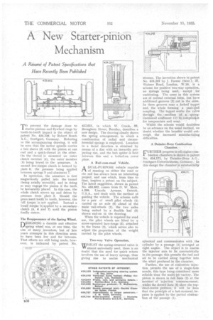
Toprevent the damage done to starter-pinions and flywheel rings by tooth-to-tooth impact is the object of Patent No, 434,248, by Robert Bosch A.G., Stuttgart, Germany. Referring to the accompanying drawing, it will be seen that the motor spindle carries a free sleeve (3) with the pinion at one end and a quick-thread at the other. On the thread is mounted an inner clutch member (4), the outer. member (1) being keyed to the armature. A. secorid low-torque clutch is formed by plate 6, the pressure being applied between springs 5 and abutment 7.
In operation, the armature is first magnetically pulled into the tunnel (being axially movable), and in doing so may engage the pinion if the teeth be favourably placed. In this case, the whole clutch screws up and drives by Pressure from• plate 2. Should the gears meet tooth.to tooth, however, the full torque is. not applied. Instead a lessri. torque is-applied by a secondary. clutch .(4, 6 and 7) until the pinion finally enters.
The Reappearance of the Spring Wheel. DESIGNI .a durable and effective spring wheel was, at one time, the aim of many . inventors, but of late years attempts in this direction seem to have been. few and far between. That efforts are still being made, however, is indicated by patent No. 433,031, in which W. Crook, 89, Brougham Street, Burnley, describes a new design. The drawing clearly shows the spring arrangement, in which a combination of radial and circumferential springs is employed. Location in a facial direction is obtained by means of a disc with an inwardly projecting rim, and the hub spider is held between this and a bolted-on cover plate.
A Rail-cum-road Vehicle.
ADUAL-PURPOSE vehicle capable of running on either the road or the rail has always been an interesting project, and one which, from time to time, inspires a. patent on the subject. The latest suggestion, shown in patent No. 433,602, comes from D. W. Main,' 4,209, -Lincoln Avenue, Detroit, U.S.A., and deals with the method of guiding the vehicle. The scheme calls for a pair of small pilot wheels (4). carried on an axle (6) ahead of the mainrailLwheels (I), -the two axles being united by a flexible leaf (5) shown end-on in the drawing.
When the vehicle is required for road use, the pilot wheels are lifted by a screw-operated lazy-tongs (2), attached to the frame (3), which serves also to adjust the proportion of the weight carried by the pilot wheels.
Two-way Valve Operation.
W/HILST the spring-returned valve is WV almost universally used, there is no doubt that the need for quick, return involves the use of heavy springs, thus giving rise to undue mechanical
stresses. The invention shown in patent No. 434,247 by J. Fareso (Senr.), 37, Wainer Road, London, W.10, 15 a scheme for positive two-way operation, no springs being used, except for cushioning. The cams in this system are of normal external form, but have additional grooves (2) cut in the sides. In these grooves runs a forked tappet end, the whole forming a push-pull coupling. Tin tappet works the valve through the medium of a springcushioned abutment (1) to cornpens4te for temperature and wear.
Whilst the scheme would doubtless he an advance on the usual method, we doubt whether the benefits would outweigh the increased • manufacturing difficulties.
A Daimler-Benz Combustion Chamber.
FURTHER progress in oil-engine comblistion chambers is shown in patent No. 434,171, by Daimlei-Benz A.G., Stuttgart-Untertiirkheim, Germany. In this design the chamber is substantially
spherical and communicates with , the cylinder by a passage (1), arranged at right angles. The object is, to enable the injector axis to lie ,ceneentriCally in the passage; this permits the fuel and air to be carried along together into the whirl produced in the chamber.
Further, the use of concentric injection permits the use of a single-hole nozzle, this type being considered more reliable than the multi-jet 'variety. The piston is shown in full. lines (2) at the Mon-tent' of injection' 'commencement, whilst the dotted line.s (3):shoi,v the .topdead-centre .position; it will he Seen that the prinCiple of a last-momenOmpulse is applied by the partial obstruction of the pasSage (1).