


A LIFEGUARD and a SPLASHGUARD by the L.G.0 C.
Page 34
If you've noticed an error in this article please click here to report it so we can fix it.
A Résumé of Recently liublished Patents.
There is a couple of interesting patents this week registered in the name of Mr. 0. J. Shave and the London General Omnibus Co., Ltd., and describing an arrangement of lifeguard and splashguard respectively.
The former is a very complete device, and extends from the front edge of .a rear wheel on one side of the bus right round, across the front of the chassis, to th.s; foremost edge of the other rear wheel. There is a front guard which consists of a slatted fendee mounted on pivots on the chassis frame in such a manner that, while normally held with its lower edge a few inches clear of the ground, in which position it is maintained by means of springs, it will, on contact with an obstruction, rapidly lower itself until its underside is practically in contact with the floor. Each front wheel is securely guarded by a combination of slatted side guard and wing. Each of the wings is extended, both before and behind the wheel, so that it Comes to within a short distance of the level of the ground, while the tips of these enlarged wings are also extended laterally towards the chassis, so that even when the steering gear is locked over to the fullest extent in either direction there is practically no gap between the wing and tho front guard on the one hand, or the wing and the side guard on the other.
The last-named extend, one on each side of the chassis, from a point just he. hind the front wings until they are close to the outer front edges of the rear wheel Ivies. The bottom member of each of these side guards is mounted so that it is free to rise and fall somewhat with respect. to the remainder of the guard, being normally maintained, however, in the lowest possible position by means of suitably arranged springs. The object of this is to allow of freedom for this .portion of the guard to surmount an obstruction whilst at the same time keeping it. in the ordinary way sufficiently close tost.he ground to protect any person with whom it. may come in contact. A door is formed in the side guard 60 that access may -be had to portions of the mechanism of the chassis without need for dismantling the whole guard.
It should be pointed out that the guards on the front wheels are so mounted that they swing with those wheels when the latter are moved for the purposes of steering the vehicle. Particular attention has been paid in the design of the fastenings of these guards to the need for preventing rattle in the event of wear, which is, of course, unavoidable, taking place. The front guard is mounted on a pair of bearings attached to the side-members of the chassis. These bearings are tapered, and the levers which carry the guard have tapered holes bored in them to correspond. The levers are held up to the bearings by means of light springs, which continually press the two cones together. Similarly those brackets which maintain the guards for the front wheels are mounted on pivots which are nearly vertical, being. as a matter of fact, disposed and inclined so that they are in line with the steering pivots of the front axle. Each guard is mounted on a pin on which P34
are a, pair of opposed conical sleeves which engage withseorresponding bored holes in the bracket forming, a part of the guard. The pair of sleeves is under the control of a, spring which, continuously forces the conical parts into close .relation one 'with another, so that wear is automatically taken up.
The splashguard is a short pad of chain mail or come similar flexible material, which is carried upon a horizontal bar in such a manner that normally it takes up a position just outside the wheel and almost in contact with the ground, near that part of the circumference of the wheel which actually does rest. upon the
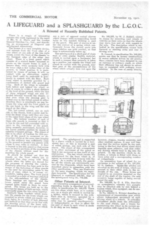
ground. The splashguard is supported by a sleeve which is carried by a horizontal bar ; on this is mounted a pair of coiled springs, one each side of the sleeve. The object of this arrangement is to allow movement of the guard so that it can sum-mount or free itself of any. obstruction. The bar which carries the splashguard for the front wheelis, of course, 60 mounted that it turns with the wheel. As a matter of fact, the guards' for all the wheels are conveniently carried by the lifeguards, which have been described above in connection with the other specification. They are illustrated on the same drawing, which we reproduce herewith. The specification for the lifeguard is numbered 169,507, that of the splashguard Leing No. 169,508.
Other Patents of Interest.
An interesting arrangement of internal. expanding brake is described by S. E. Alley, in specification No. 169,479. There are two shoes which bear, as is customary, on a single pin which is carried by
a spider' which is secured to the wile.shoeEach• shoe is, however, operated by a
separate cam or " eapander." These
cams may be operated simultaneously, or independently, so that in effect the one pair of shoes in each wheel is made to do clay as two bac:Ekes. No. 148,554, by W. J. Riddell, relates to means for mounting road wheels of vehicles on their axles sothat the wheels may move fore and aft with respect' to the aide. The description which is embodied in the specification covers both feyward or steering axles and rear or driving axles: R. Conrad, in specification No. 148,255, points out that an former constructions of motor+ vehicles driven by air screws, those vehicles have been designed to run on rajlWays or ordinary roads, on, which their efficiency has not shown to advaiatags as -compared -with ordinary trans. missions.' In the case f. sandydeserts,
however, steppes, marshy countries, and other roadless regions, it may well happen that'the reverse might be the case, owing to the-fact that direct wheel drive depends upon adhesion, and that ordinary driving wheels tend to dig into the ground. In the machine which he describes, a vehicle is fitted with three or more axles and a corresponding number of widetwheels.
An interesting type of wheel for an agrimotor is the subject of No. 157,319, by G. Szakata. Spade-like stialfes are mounted on the ends of levers, which are secured at their other ends to the un derside of the rim. These levers are coupled to an eccentric mounted on the end of the shaft of the tractor, the said eccentric.; being capable of being moved round the axle.
No. 169,650, by G. A. File, describes an arrangement whereby two ploughs may be attached side by side behind a tractor which,..thus equipped, can do oneway ploughing. In No. 169,546 L. Krieger describes an arrangement of transmission gear which allows independent movement of each driving wheel of a vehicle. It, emb,odies articulated shafts from the differential to the road wheels, and a means for maintaining the wheel in its correct angular position with regard to the chassis.