


THE RIDLEY ONE-TON CHASSIS.
Page 12
Page 13
Page 14
If you've noticed an error in this article please click here to report it so we can fix it.
A New Design Lending Itself to Production in Large Quantities.
IN -VIEW OF the keen competition which Will prevail after the, war in all trades, it is obvious that -the deniand' for commercial vehicles will be a pressing one. To build 'up our fortunes anew; and to make good the terrible wastage of wealth which has been entailed by the war, it is essential that home products he utilized to the fullest possible extent, and that imported goods be purchased only in the event of a failure on the part of -British manufacturers to meet the home demand. • It is inevitable, however, given equality of performance and reliability, that the chassis which will find most purchasers is that which cab be sold at the lowest price. The Maximum of productive economy iseonly attainable by the employment of standardization and by manufacturing in large quantities.
It will generally be conceded that, even with the _facilities accumulated during three of more years of -war-work extensions, few English factories are equipped for quantity production of vehicles on the British plan, viz., manufacture
the complete chassis. The alternative, assembly in one works -of Units made by specialists in their, own line, appears to be an attractive one. . All types and sizes of chassis are amenable to this treatment, but it is essential that the designer should have, in the first place, a full knowledge of the requisites for successful construction of such a chassis.
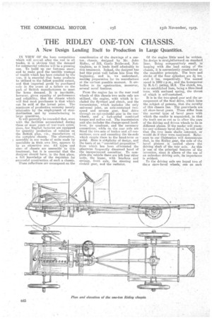
These reflections are consequent on the consideration of the drawings of a, oneton chassis, designed by Mr. John Ridley, of 315, Castle Bou'levard, Nottingham, as it lends itself admirably to this treatment. Indeed, the designer has had this point well before him from the beginning, and is, we understand, making preparation for its manufacture at the earliest possible moment. . It embodies in its construction, moreover, several nover features.
From the engine fan to the rear road wheels of this chassis-two units only are utilized, the engine, with which is in-eluded the ilyWhoel and clutch, and the transmission, which includes the only universal joint, an axle-contained twospeed and reverse gear, final drive through an epi-cycloidal gear in the rear wheels, and a fork-endedcombined torque and radius rod. The transmission unit also includes the change-speed handlever, its quadrant,. and the necessary connections, while on the rear axle are fitted the two sets of brakes and all connections; save and excepting the tie-rods which (maple them to the hand-leVer or pedal. Here is siitplicity of design, and the basis of an " assembled proposition from which has been eliminated the otherwise frequently discerned hand of' theinexperienced assembler. To complete the smhicle there are Left four other units, the frame, with brackets and springs, front axle, the steering and control gear, and the radiator. Of the engine little need be written. Its design is straightforward on standard_ lines. Being comparatively small, in keeping with he load rating of the chassi.s., it is conveniently, constructed on the monobloe principle. The bore and stroke of the four cylinders are 34 ins. and 5 ins, respectively. The normal speed is 1000 rpm. and the horsepower. by R.A.C, rating, 1.6.9. , The clutch, too, is on eStabashed lines, being a fibre-lined 'Cone. with en-closed spring, the thrust of .which is self-contained.
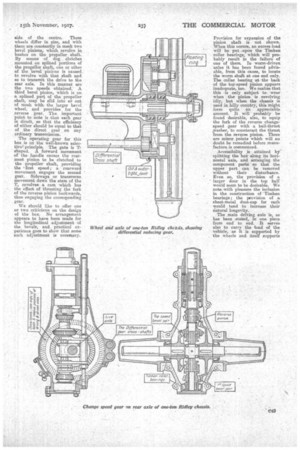
It is in the two-speed gear and the arrangement of the final drive, which form the subject of patents, that the novelty of this chassis lies.TIM gearwheels are all skew-bevel gears. These differ from ' the normal type of bevel gears with whichthe reader is acquainted, in that the teeth are so emit as to allow the axes of the driving and driven wheels to lie in different planes. If the reader will examine any ordinary bevel drive, he. will notethat the two mainshafts intersect, or would do if they were continued. Reference to our illustration will demonstrate that, in the Ridlev. gear, the axle of the bevel pinions . is carried above the driving shaft of the rear axle. As this is 'one of the principal features of the invention, since it allows of the use of an unbroken driving axle, its importance is evident.
To the driving axle are keyed two of thee skew-bevel wheels, one on each
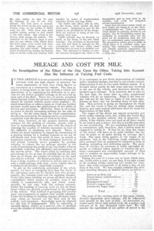
side of the centre. These wheels differ in size, and with them are constantly in mesh two bevel pinions, which revolve in bushes on the propeller shaft. By means of dog clutches mounted on splined portions of the propeller shaft, one or other of the bevel pinions is caused to revolve with that shaft and. so to transmit the drive to the rear axle. In this manner are the two speeds obtained.A. third bevel pinion, which is on a splined part of the propeller shaft, may be slid into or out of mesh with. the larger bevel wheel, and provides for the reverse gear. The important point to note is that each gear is direet, so that the efficiency of either should be equal to that of the direct gear on any
• ordinary transmission.
The operating gear for this box is on the well-known selective' principle. The gate is T-shaped. A forward movement of the. handle causes the rearmost pinion to be clutched to the propeller Shaft, providing the • ff.rst speed; a rearward movement engages the second gala.. Sideways or transverse movement down the stem of the T, revolves a. cam which has the effect of thrusting the fork of the reverse pinion backwards, thus engaging the corresponding gear.
We should like to offer one or two criticisms on the design of the box. Is.To arrangement appears to have been made for the longitudinal adjustment of the bevels, and practical experience goes to show that some such adjustment is necessary. Provision for expansion of the pinion shaft is not shown. When this occurs, an excess load will be put upon the Timken roller bearings, which will probably result in the failure of one of them. In worm-driven axles it has been found advisable, from this cans; to locate the worm shaft at one end only. The collar bearing at the back of the top-speed pinion appears inadequate, too. We realize that this is only subject to wear when the pinion is revolving idly, but when the chassis is used in hilly country, this might form quite an appreciable amount. It will probably be found desirable, also, to equip the fork of the reverse changespeed gear with a ball-thrust washer, to counteract the thrust from the reverse pinion. These are minor points which will no doubt be remedied before manufacture is commenced.
Accessibility is attained by' splitting the 'box along its horizontal axis, and arranging the component parts so that the upper part can be removed without their disturbance. Even so, the provision of a larger door in the top half would seem to be desirable. We note with pleasure the inclusion in the construction of 'Timken bearings; the provision of a sheet-metal dust-cap for each would tend to increase their natural longevity. .
The main driving axle is, as has been stated, m one piece from end to end. It serves also to carry the load of the vehicle, as it is supported by the wheels and itself supports the ,axle casing, . as may be seen
i-ef,erring to one of • our illustrations: The Anal driv.e is unusual. Inside the drums op the axle casing are floating rings; on the insides of w.hich teeth are cut. With these cogs mesh satellite pinions carried. on phi bolted to the road. wheels. Sun wheels in the driving shaft engage the pinions. The refistance of the -floating rings is such that the aim wheels, when driven from the bevel gears, carry round With them the planetarS, pillions and, in consequence, the road Wheels.' Differential action ia obtained" by making thefloating rings of &wide width and coupling them
together by means of supplementary planetary pinions and long shafts.
The brakes take effect, side by aide, on the drums which enclose the final drive gears. gornponsating gear for the brakes is not provided forin the design. Both are depicted as being of the contracting band type.
Useful criticism may be directed, we think, at the design of the rear wheel bearings. The provision of bicycle type COILS and ball racesto account for the considerable end thrusts 'which these bearings have to carry is of doubtfutwis= dom. The adherence to Timken or shill%Jar bearings throughout the whole uf the
transmission and on both axles is, we consider, well worth the designer's serious consideration. • • • , Apart from the minor points which we have raised, the design is; on the whole commendable one. • There are reasons,• which should be 'perfectly obvidim to our • readers, why its manufacture cannot immediately be proceeded with,. but the plans for its prod action after the war '
• are we understand, under consideration. . The prespative Selling-price if L160,at which figure it is excellent value, . pre= Burning that satisfactory workinanship and suitable materials supplement, the 'design. It should undoubtedly Command a rea,dy sale.