


Brakes, 3
Page 74
If you've noticed an error in this article please click here to report it so we can fix it.
PRACTICALLY all heavy commercial vehicles are fitted with air-operated brakes, and on reflection this is not surprising. Air is readily available, ills free, it does not deteriorate in service, it is easily filtered and it can be discharged to the atmosphere after it has served its purpose without causing any pollution, except for the characteristic hiss with which everyone is familiar.
It has the added advantage that the air stored for the braking system can also be used as a source of power for other operations such as opening doors on buses, sounding horns, and operating windscreen wipers and differential locks.
However complicated air braking may appear the whole system can be divided into four groups: Group 1. Compression and storage Air is compressed by an engine-driven compressor and stored under pressure in reservoirs. An unloader valve or governor is fitted to control the air pressure to within safe and convenient levels. When the compressor charges the reservoirs to the maximum pressure specified, the unloader valve or governor operates so that the compressor no longer pumps air but is allowed to idle.
As the stored air is used for brake application, the pressure in the reservoirs drops, and when it has fallen about 0.710 1.0 bar (10 to 15 psi) the compressor is allowed to operate again to recharge the system. A safety valve is fitted to guard against an excessive and dangerous build up of pressure. Group 2. Control Control valves, with graduated output, are fitted for applying the brakes and these may be hand or foot operated.
Group 3. Actuation The most usual type of actuator is the diaphragm chamber which converts the energy of the compressed air into a mechanical force to apply the brakes.
Group 4. Indication The Construction and Use Regulations require vehicles fitted with air or vacuum brakes to be provided "with a warning device so placed as to be readily visible to the driver of the vehicle when he is in the driving seat to indicate any impending failure or deficiency in the vacuum or pressure system". Pressure gauges are provided to comply with this requirement and, in addition, a low pressure warning device (usually a buzzer, although semaphore arms have been used) is fitted to give warning to the driver if, for some reason, the compressor is unable to maintain normal working pressure in the system. Stop lights are also required by law and these are operated from a switch in the delivery pipe of the air brake circuit.
All this equipment will be described in detail in future articles.
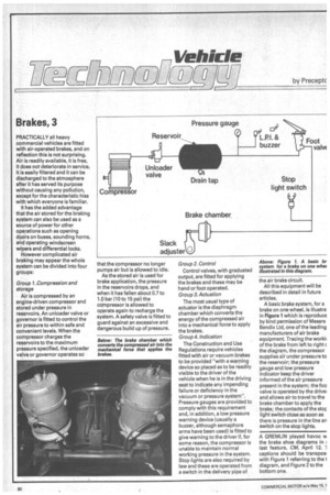
A basic brake system, for a brake on one wheel, is illustra in Figure 1 which is reproduce by kind permission of Messrs Bendix Ltd, one of the leading manufacturers of air brake equipment. Tracing the worki■ of the brake from left to right the diagram, the compressor supplies air under pressure to the reservoir; the pressure gauge and low pressure indicator keep the driver informed of the air pressure present in the system; the foe valve is operated by the drivel and allows air to travel to the brake chamber to apply the brake; the contacts of the stor light switch close as soon as there is pressure in the line an switch on the stop lights.
A GREMLIN played havoc the brake shoe diagrams in last feature, CM, April 12. 1 captions should be transpos with Figure 1 referring to the 1 diagram, and Figure 2 to the bottom one.