


A GARRETT TRAILER.
Page 30
If you've noticed an error in this article please click here to report it so we can fix it.
A Résumé of Recently Published Patents.
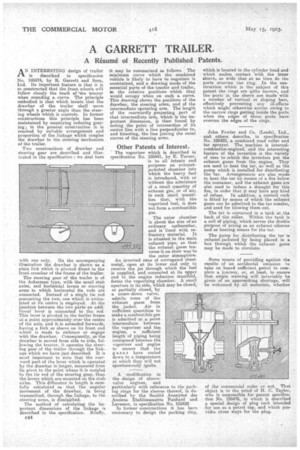
A N INTERESTING design of trailer 1-1 is described in specification No. 195574, by R. Garrett and Sons, Ltd. Its important feature is that it is so constructed that the front wheels) will follow closely the track of 'the tractor when rounding a curve. The principle embodied is that which insists that the drawbar of the trailer shall move through a greater angle than the steering wheels which it controls. In former constructions this principle has been maintained by employing redueing gearing; in the present construction it is reached by suitable arrangement and proportion of the linkage which couples the drawbar to the steering mechanism of the trailer.
Two constructions of drawbar and steering gear are described and illustrated in the specification : we deal here with one only. On the accompanying illustration the drawbar is shown as a plain link which is pivoted direct to the front crossbar of the frame of the trailer.
The steering gear of the trailer is of. the Ackerman type, with the usual stub axles, and horizontal levers or steering arms to which horizontal tie rods are connected. Instead of a. single tie rod connecting the two, one which is articulated at its centre is employed. At the junction between the two parts an addi• tional lever is connected to the rod This lever is pivoted to the trailer frame at a point approximately over the centre of the axle, and it is extended forwards, having a fork or sleeve on its front end which is made to embrace or engage with the drawbar. Consequently, as the drawbar is moved from side to side, following the tractor, it operates the steering gear of the trailer through the linkage which we have just described. It is imast important to note that the rearward part of the. lever which is operated by the drawbar is longer, measured from its pivot to the point where it is cotipled to the tie rod of the steering gear, than the levers which are mounted on the stub axles. This difference in length is carefully calculated se that the angular movement of the drawbar, in being transmitted, through the linkage, to the steering arms, is diminished. • The method of calculating the important dimensions of the linkage is described in the specification. Briefly, it may be summarized as follows. The minimum curve which the combined vehicle is likely to have to negotiate is ascertained, and a drawing made of the essential parts of the tractor and trailer, in the relative positions which they would occupy when an such a curve. This drawing shows the positions of the drawbar, the steering arms, and of the intermediate operating arm. The length of the rearwardly projecting part of that intermediate arm, -which is the important dimension, is then found by noting the point of intersection of its centre line with a line perpendicular to, and bisecting, the line joining the outer curves of the steering arms.
Other Patents of Interest.
The vaporizer which is described in specification No. 195441, by E. Turner, • is to all intents and purposes an exhaustjacketed chamber into which the heavy fuel is introduced, with or without the admixture Of a small quantity of exhaust gas, or of air, in such small quantities that, with the vaporized fuel, it does not form a combustible gas, The outer chamber is about. the size of an ordinary carburetter, and is lined with refractory material. It is situated in the main exhaust pipe, so that the exhaust gases traverse it on their way to the outer atmosphere. An inverted cone of corrugated sheet metal, open at, its lower end only to receive the jet through which the fuel is supplied, and connected at its upper end to the engine induction manifold, forms the vaporizing chamber. A small aperture in its side, which ma.y be closed, or partially closed, by a screw-down valve, admits some of the exhaust gases from the jacket. Air in sufficient quantities to make a combustible gas is admitted at a point intermediate between thevaporizer and the engine, • a sufficient length of piping being interposed between the vaporizer and engine to ensure that the gases have cooled down to a temperature at which they will not spontaneously ignite.
A modification in the design of sleevevalve engines, and particularly with reference to the is rings for the sleeves thereof, s de scribed by the Societe Anonyme des Anciens Etablissements Panhard and Le.vaasor, in specification No. 192428 In former constructions it has bee!i customary to design the packing ring, which is located in the cylinder bead and which makes contact with the inner sleeve, so wide that at no time do the ports overrun the ring. In the construction which is the subject of this patent the rings are quite narrow, and the ports in the sleeve are made with a number of vertical or sloping bars, effectively preventing any ill-effects which might otherwise accrue awing to the narrow rings getting inside the ports when the edges of those ports have overrun the edges of the rings.
John Fowler and Co. (Leeds), Ltd., and others describe, in specification No. 195425, a combined road roller and tar sprayer. The .machine is internalcombustion-enginecl, and the interesting feature of the invention is the variety of uses to which the inventors put the exhaust gases from the engine. They are used to heat the tar, as 'well as the pump which is installed for distributing the tar. Arrangements are also made to heat the tar by means of a fire below the container, and the exhaust gases are also used to induce a draught for this fire, in order that it may burn any kind of refuse. In addition, a control cock is fitted by means of which the exhaust gases can be admitted to the tar nozzles, and used for blowing them out.
The tar is contained in a tank at the back of the roller. Within the tank is a coil of piping,, which serves the double purpose a acting as an exhaust silencer and as heating means for the tar.
The pump for distributing the tar is exhaust-jacketed by being placed in a box through which the exhaust gases may be made to circulate.
. Some means of providing against the results of an accidental omission to take on board sufficient petrol to complete a journey, or, at least., to ensure that ample warning will invariably he given of an approaching shortage, will be welcomed by all motorists, whether of the commercial order or not. That object is in the mind of H. C. Taylor, who is responsible for patent sPeetfication No. 195476, in which is described a special design of plug cock intended for use as a petrol tap, and which provides three ways for the plug.