


Vehicle with a Variable Track
Page 66
If you've noticed an error in this article please click here to report it so we can fix it.
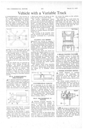
INORTHODOXY is the keynote ot %.--) a vehicle design shown inpatent No. 767,420 (Rheinmetall A.G., Rather Strassc 110, Dusseldorf, Germany). The chief point of the design is that the track width is variable within wide limits. Suggested uses for such a vehicle are for cross-country work over rough
ground, for carrying oversize loads on the -road, or for one-sided loads such as mobile Cranes have to withstand.
The drawing shows a crane carrier according to the invention. The wheels are all carried on outriggers (1) which are capable of swinging about pivots (2). The dotted-line view shows them expanded to act as a large base for the crane.
All the wheels may be powered by propeller shafts running through the outriggers. All wheels are steerable and their mechanism is interconnected so that they move in unison. The outriggers can be locked for normal running or Swung. out either by hand or by power. They may even be moved during travelling by controlled selective steering.
DUAL SUPERCHARGING ARRANGEMENT
ALL internal combustion engines give a reduced torque at low speed as distinct from a steam engine which gives its maximum torque at a standstill. A supercharging scheme, claimed to impart at least some of the steamengine characteristic to an oil engine, is
shown in patent No. 766,152. (Leyland Motors, Ltd., Suffolk House, Laurence Pountney Hill, London, E.CA.) Referring to the drawing, a centrifugal blower (1) is driven-by an exhaust turbine and .feeds the engine via a butterfly throttle (2) and a cooling unit (3). A parallel pipe system contains a Roots-type blower (4) driven by the engine through a releasable clutch.
The positive displacement Roots blower is used to charge the engine at_ low speed, the butterfly valve being then closed. At high speeds, the exhaustdriven turbine becomes effective and the butterfly valve can then be opened and the Roots blower clutch (5) freed. The effect is to provide a• reasonably constant air charge whatever the engine speed may he.
The working of the butterfly valve and the control of the clutch are automatically performed by a governing device.
PLASTICS VAN BODIES
PATENT No. 767,543 (T. Hunter, 7 Osborne Road, Brimsdown, Middlesex) gives information on a method of constructing van bodies from reinforced plastics panels. As this material is translucent, it is unnecessary to provide windows in the body.
Tile drawing shows the means for attaching the plastics sheets' (1) to the body uprights. The latter (2) pre made from lengths of extruded light-alloy section consisting of a channel portion with outstanding flanges. The longitudinal stiffeners (3) are riveted to these flanges, which also carry interior slats (4) for protecting the panels against damage from the load.
The plastics sheets have turned-in edges which are fixed to the channels by rivets 5. Mating edges of the sheets are united by a moulded rubber strip (6).
CYL1NDER-HEAD COOLING
IT is important in an oil engine to prevent overheating in the region of the injector, and patent No. 768,146 discloses a -cooling scheme in which deflecting walls are provided in the water jacket to ensure that this region receives adequate flow. (Ricardo and Co. Engineers (1927), Ltd., 21 Suffolk Street, London, S.W.1.) HEAT TRANSFERENCE IN PISTONS APISTON designed specially for compression-ignition engines is shown in patent No. 767,328 (L. Gardner and Sons, Ltd., Barton Hall Engine Works, Patricroft, Manchester). The chief aim of the design is to provide better heat transfer away from the ring region to the skirt.
From the crown of the piston there descends a pair of vertical, walls which have, at point 1, a considerable thickness; this thickened portion extends as far across the piston as the cylinderbore will permit.
The walls, as they reach below the gudgeon-pin, thin out (as shown at 2) and merge into the skirt. The ring region (3) does not, therefore, lie directly in the heat-flow path from the combustion chamber to the skirt.
A BRAKE MASTER CYLINDER
A MASTER cylinder in which only
a single port is provided for replenishment of the fluid when the piston is in the returned position is described in patent No. 768,162, which comes from Alfred Teves MaschinenUnd Artnaturenfabrik K.G., 41-53 Rebstockerstrasse, Frankfurt am Main, Germany. The fluid flows through this port and through passages in the piston.
A PETROL ECONOMY DEVICE rtA UNIT designed to promote economy by improving the vaporization of the petrol forms the subject of patent No. 766,181. (W. Pickles, 85 Cecil Avenue, Horton Park, Bradford.)
The device consists primarily of a small centrifugal blower (I) driven by an electric motor (2). The inlet flange (3) is connected to the carburetter, whilst the tangential outlet (4) leads to the induction pipe.
Whitt the design is definitely that of a blower, the specification points out that some or all of the blades may be perforated, the object being to reduce the blowing action and increase the turbulence around the fuel droplets suspended in the air. stream.