


Progress in Hydraulic Couplings
Page 60
If you've noticed an error in this article please click here to report it so we can fix it.
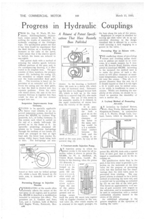
FROM Dr. log. Wach, 57, See . strasse, Kilcbberg-Zurich, Switzerland, comes patent. No. 423,347, describing the results of researches into hydraulic couplings of the Fottinger type. The specification points out that it has been found by experiment that the fluid friction on a revolving disc increases. as the cube of the speed, which means that if the relative speeds be halved, the losses are reduced to one-eighth.
This patent deals with a method of reducing the relative speeds between different portions of the gear, and, in the accornpanyiag drawing, it is illustrated in its simplestform. The gear consists of three members, the primary runner (1), including the casing (3), the secondary or output runner (2), and the -brake-controlled fluid guide
(4). The invention is based on the provision of an extended wall (5) between the casing and the fluid 'guide, so that the fluid is divided into two separate portions. ,prom the cubic rule stated above, the sum of the two separate frictions is together less than would be that of the two streams merged into one.
Suspension Improvements from Germany.
STATED to be specialty applicable to heavy road vehicles, is an improved suspension system, described in patent No. 423,219, by Gothaer Waggonfabrik, A.G., of 'Gotha, Germany. In this system each wheel is carried on the end of a sturdy bell-crank (4) pivoted on to the frame at 5. An upwardly, projecting abutment (2) presses on to transverse leaf-springs through the medium of two bosses (3) which are arranged so that at light load only the lower boss reaches the spring, whilst heavy loads bring both to bear. . The leaf-springs, are rein
forced at their ends by helical springs (1), whilst a hook (6), formed on the main arm, is intended to check rebound.
Preventing Damage to Injection Nozzles.
OVERHEATING of the nozzle often adversely affects the nature of the fuel spray on oil engines, and in patent , No. 423,126 is described :a modification intended to minimize this effect. The patentees are L. Gardner and Sons, Ltd., and J. Gardner, both of Barton Hall Engine Works, Patricroft, Man
chester. In the drawing, a hardened vtalve (4) seats in a sleeve (3), which is also of hardened steel. Surrounding this sleeve is a flanged bronze bush (2), which is held up to the main body by a screwed ring (1), also made of bronze. The use of this metal in the assembly results, it is claimed, in the rapid conduction of excess heat from the vicinity of the nozzle.
It is practicable to make the bash a good fit on the sleeve, whilst clearance . of the latter in the main casting would be ri a voidable. Good contact between the bush and the casting is ensured at the cone joint; by Way of the screwed ring (I).
A Constant-stroke Injection Pump.
AN injection pump in which the piston stroke is the samelor all injection values is shown in patent No. 422,850, by W. A. Sheldrkk, 12, Church Road, Canton, Cardiff. Referring to the draivi ig, when the pisto (1) descends, a vacuum is formed at its head until the ports (2) are uncovered, after which oil enters and fills t h e compression space. Upon the rise of the piston the oil is compressed and injection occurs until the ports (4) move into register with an angular chamber in the control valve (3), after which surplus oil is returned to the supply passages, via
the bore along the axis of the piston.
Regulation of output is: obtained by moving. .tilike slide valve (3) in an upand-down direction; in the • design described this is effected by a wormwheel carrying a fork engaging in a groove in the valve. "
Preventing Slap or Seizure with. Pistons. •
THE conflicting claims. of preventing seizure and avoiding undue slackness in pistons are stated to be overcome, in a simple manner, by I. Ashcroft, 35, Avenue Road, Staines, whose patent is numbered 423,255. According to the inventor, the method used is to make the piston of such a diameter as will allow clearance at maxiMUM temperature, exCept for a narrow
rib' near the crown. This rib is of greater diameter than the rest, for if it should expand so that it is too tight a fit it Would soon be rubbed away, as its width is insufbcient to cause a seizure. Whilst not doubting the simplicity of the scheme, we should be inclined to question the durability of sum . a narrow rib.
A Leyland Method of Promoting Air.swirl.
N invention by Leyland Motors, !Ltd., Ham Works, Richmond Road, Kingston-on-Thames, in conjunction with J. T. Naylor, Hough Lane, Leyland, Lanes, which is described in patent No. 423,316, deals with a special form of inlet port that is claimed to impart a considerable swirl to the incoming air.
The specification states that, in the past, it has been usual to provide a l.rojection on the underside of the inlet valve for the purpose of promoting swirl, but this method has the disadvantage that the inlet valve must be
prevented from rotating. The suggested scheme is-claimed to be a better method of achieving the same end, and is carried out by providing an extended lip (1) on one side of the inlet port. This leaves an approximately oval section of port eccentric with respect to the valve-stem, and is recommended to be used in conjunction with a conical combustion chamber formed in the crown of the piston.
An additional advantage is the greater simplicity of the operation of making the valve.