


SUSPENSION SYSTEMS
Page 32
If you've noticed an error in this article please click here to report it so we can fix it.
A Résumé of Recently Published Patents.
There are two specifications this week dealing with the suspension systems of motor vehicles. They are not, either of them, likely to be applicable to any extent in connection with heavy motor vehicles, but are, nevertheless of interest in respect of the possibility i y of their adaption to the requirements of light vans.
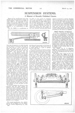
One, No. 158097, is a modification of that type of suspension in which the axle i of the vehicle s secured to the ends of the long arms of a pair of bell-crank levers, the short ends of which have their movement controlled by sets of springs which may be of any type, but preferably, and generally, are coil springs. In the present instance the inventor makes the long arms of the bellcrank levers themselves serve as springs, by converting them into quarter-elliptic laminated, or leaf springs, and thus combines in one construction the advantages of leaf and coil springs. As may be seen on reference to one of the accompanying illustrations, the arrangement is quite a simple one. A quarter-elliptic spring of familiar type and design is secured at its outer i514.1 to the axle, and at the butt or inner end to a bracket. That bracket is pivotally attached to the frame of the chassis by being mounted on a spherical journal, which is part of a bracket bolted to a side member of the frame. In one, with the bracket to which the spying is secured, is a downwardly depending arm 'which forms, in effect, the short arm of the bell-crank lever. Another bracket, rigidly .bolted to the frame of the chassis, carries a smaller arm, and the ends of these two arms are so arranged that they come in line with the other, and support, through the medium of a long spindle, six coiled springs arranged in pairs, one pair is thrust between the two arms, the other pairs outside the arms, one pair on each side of them.
It will be realized, by reference to the . drawing, that the outer springs are adapted to absorb shocks caused by the axle being thrust upwardly, whilst the 'centre ones absorb rebound shocksin the reverse direction. When The moyeinent of the axle is other than vertical, or when it is caused by other than end thrust: that is to say, when the movement Is such that torsional stress would be carried to the frame or axles, that stress is relieved by the free movement of: the bracket to which the spring is attached, on the spherical journal. The patentee is S. S. Shears.
The second specification, No, 158114, is by A. H. R. Fedden, L. F. G. Butler, and the Cosmos Engineering Co., Ltd.
B28
It refers to that system of -springing which was exemplified in the Cosmos ear, which made its first appearance at the Olympia Show of 1919. This, again, like the last specification, has reference to the type of springing in which the axle is suspended from the long arms of bell-crank levers, the short arms of which are controlled by coil springs. In this case, however, the bell-crank levers
are disposed transversely to the frame of the vehicle, and the short levers act on a single spring or a pair of springs between their ends.
The inventor points out that in respect of ordinary constructions the front axle would normally be restrained by a radius rod or pair of railius rods, which, for practical reasons, would be comparatively short. The result would be that, as the axle moved up and down, under the influence of road and load inequalities, and under the control of the springs, it would move in the arc of a circle, the radius of which would be represented by the radius rods, and in consequence the attachment to thebellcrank levers would only rarely remain in the truly vertical position in which it would be best adapted to work in conjunction witji the bell-crank levers. In order to surmount this difficulty, the patentee substitutes, for the radius rods, an arrangement which compels the axle always to move in a vertical direction. This arrangement involves the substitution, for the radius rods, of two pairs of spiing steel arms. The individual members of each pair are mounted in parallel one above the other, and firmly secured at their front ends to the axle, and at their rear ends to the frame. Thus arranged they constitute a parallel link motion, and provide for the truly vertical movement of the axle as is required.
Other Patents of Interest.
S. S. Guy, in specification No. 1581C4, describes an arrangement of carburetter end water circulating pipes, in which the passage between carburetter and induction manifold is taken through the outer pipe of the water circulating system. He claims that, as arranged, the whole of the circulating water, which is there at its hottest, has to pass. round the pipe ,conveying the explosive mixture to the engine, with results not only beneficial as regards the vaporizing effect, but also in re,speet of the cooling effect on the circulating water.
No. 158074, by F. T. Skippens, describes an arrangement by means of which the steering and control of a Ford car may be transferred from the near to the off side.
The lifting jacks, which are the subject of patent No. 158049, by A. E. Ford, are the type which are permanently secured to the axle. There may he three or four .such jacks, each consisting of a jointed rod fitted with an eccentrically pivoted foot with a corrugated surface.
It is claimed for the automatic ignition control, which is the subject of No. 142792, that it is more compact than any previous design, that it can be embodied into existing magnetos without difficulty, and that, owing to its light weight, very little power is required to drive the governor. The patentee is J. E. Tuseher.