


With Intent to Improve.
Page 22
If you've noticed an error in this article please click here to report it so we can fix it.
A Weekly Summary of Recent Patents, of Interest to the Maker and User of Commercial Motor Vehicles.
Selected and Abridged by H. S. Hall, A.M.I.A.E.
A Safety Control Gear for Electrics.
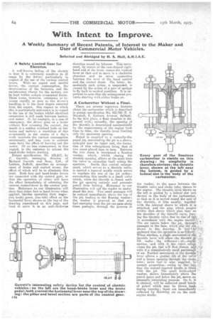
A well-known failing of the electric is that it is extremely sensitive to ill usage by the driver, particularly in respect of the use of the various control levers. Withan expert and careful driver, the current consumption, the deterioration of the batteries, and the maintenance charge for the motors, can be kept within certain economical limits. These items, however, commence to increase rapidly._ so soon as the driver's handling is in the least degree removed from the expert. One respect in which this is particularly noticeable is in regard to the use of the brakes Whilst electrical connection is still made between battery d motor. If, for example, in a case of emergency, the driver pots on a brake withont first releaeing the current, the result is a sudden overload both on bat teries and motors; a repetition of this occasionally in the course of a day's work increases the current consumption enormously, and may even iii extreme eases have the effect of burning out the motor. Of no less consequence, in this regard, is the omission to release the hand-brake before starting.
Patentspecification, -No. 103,617, by F. Garrett, managing director of Richard Garrett and Sons, Ltd., of Leinton, Suffolk, describes an arrangement of brake and control levers, the effect of which will be to eliminate this 'fault. Both foot and hand-brake levers are cOnnected i th the control gear, so that tile operation of either will have the effect immediately of returning the current control-lever to the neutral posi' tion. , Reference to our illustration will show that either foot or hand levers when applied, besides operating their respective brake _gears, also take effect on the horizontal lever shown, at the' top of the drawing reproduced on this page, and tend to move it in an anti-clockwise
direction round its fulcrum. This movement, by reason of the cam-shaped righthand end of the lover, causes the vertical lever at that end to move in a clockwise direction and to sever connection betWeen the lever of the hand control and the control drum. The latter, immediately such action is suspended, is paused by -the action of a pair of springs to fly back to neutral positticm. It is important to note that the arrangement prevents starting with either brake, on.
A Carburetter Without a Float.
There are several ingenious features about the carburetter which is described in patent specification No. 103,724 (T. S. Marshall, 6, Lisburn Avenue, Belfast). In'the first place, a float chamber is dispensed with; secondly, the opening of the throttle is determined automatically by the requirements of the engine from time to time, the throttle lever limiting only the maximum opening.
Petrol is supplied to a centrally-dieposed jet, surrounding the jet is a sleeve, enlarged near its upper end, the formation of this enlargement being that. of two cones placed base to base. Between the two cones is interposed a floating washer, which, whilst closing the throttle opening, allows at the same time the valve to centralize itself within the aperture. Inside this conical enlargement, which serves as a throttle valve, is carried a tapered needle which serves to regulate the size of the 'jet orifice; surrounding this needle is a small valve which, when the throttle is Closed, seals the jet opening entirely and prevents petrol from leaking. Reference to our illustration will aid the reader to understand the text. Two small passages will lie. noticed immediately above the top of the, jet, leading to the floating washer ; the washer is grooved so -that any fuel, emerging from the jet can pass along these passages, through the grooves in the washer, to the space between the throttle valve and choke tube, thence to the engine. The throttle lever shown on the left is guided by a helical slot (net shown) in the body of the carburetter, so that as it is moved round the axis of the. throttle, it lifts axially, together with the internal sleeve to which itis attached, and the pins which project within that sleeve which pins bear on the shoulder of the throttle valve, leaving the throttle viilve free to 'iise—ctfall in accordance'. with. the .engine The air eaters below the' jet,. throuiri-e_ passages in the base, Which also are net shown in ; the.' drawing:. It A;Iti'e-fe gathered that thee op:e ra ti on is as"foliowg': When starting,-a Sligit merliernerit:lEif.tb:d. throttle lever_ will allow, the lift under .. thi infinence-F. ofweengine suction, „and, with .it..„.thee valve :wills!' closes the jet, fuel will 'flow': thence, arrijelwith it a'compfer.ativelyrkne.11 pereent of air. Further moyetneritof the' throtte lever allows a greater lift of the vali'e and a larger opening 'through the choke,: tube; more fuel ',is also supplied, in correct proportion,-. owing to the fa.0:that the central -tapere'cl needleis liffed_ with the jet. The -small knife-edged ' -washer, shown 'immediately above the petrol union and below the jet, serves an unusually interesting purpose. On it, it is claimed, will be collected small -beads of petrol which , may be blown_baiek. during running ; these are immediately collected by incoming air on the next engine stroke.