


A Self-adjusting Tappet
Page 66
If you've noticed an error in this article please click here to report it so we can fix it.
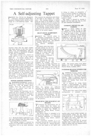
DATENT No. 747,161 (G. Shepherd, I " Alvaston," Stockport Road West, Bredbury, Cheshire) gives details of the design of a self-adjusting tappet. The
inventor states that the usual trouble with these devices is that they tend to suffer from over-adjustment, and the present scheme is specifically designed 50 that this is impossible.
The tappet consists of a barrel (1) which acts as a nut to the screwed head (2). A torsion spring (3) is biassed so as to tend to unscrew the head and so take up slack.
The head portion is arranged to rub on a concentric portion (4) of the camshaft, and the direction of rotation is such that, when it rubs, it tends to screw the head in and shorten the tappet.
In operation, should the tappet he too long, the valve-spring force would then be applied to the camshaft ring; this would set up an effective shortening action. A disadvantage seems to be the expense of machining the extra rings on the camshaft.
POWER-ASSISTED STEERING A POWERED-STEER1NG system is Cl shown in patent No. 747,135 (Ford Motor Co., Ltd., 88 Regent Street, London, W.1), the chief novelty of which is the control valve and its associated mechanism.
Two schemes are described, one in which the servo cylinder is built on to the steering box and another in which a separate booster cylinder is used. The latter is shown in the drawing.
The booster cylinder (1) has a piston that is normally in the middle, as shown at 2. Hydraulic fluid is admitted to one side and released from the other when the steering-wheel is turned.
The steering column is screwed (as shown at 3), and when turned moves a valve-sleeve (4) in an axial direction.
This controls the admission and release of the fluid in the manner of a slidevalve. The steering column is turned down for much of its length to a small diameter so that it acts as a torsion rod and gives the driver a sense of the force he is applying. A lost-motion coupling ir. the steering column enables manual operation to be restored in the event of failure of the power supply.
HEAVY-DUTY SUSPENSION SYSTEM
PATENT No. 747,119 refers to springing arrangements for heavy vehicles, particularly those made for traversing rough ground. The patentee is General Motors Corpora
tion, Detroit. Michigan, U.S.A.
The patent states that many off-road vehicles are not provided with springs because of the difficulty that attends the design of a system that will withstand the abuse. The present scheme is claimed to meet the demands.
Referring to the drawing, heavy leaf-springs (1) are used, clamped to the axle assembly by U-bolts. The springs in the example described are in. thick and 6 in. wide. They are not attached to the frame at their ends, but slide on pads (2) fixed to the frame.
When the springs are deflected upwards, the effective length shortens as the blades roil on the pads.
Rebound snubbers are provided in the form of rubber blocks (3) mounted on depending frame-brackets. As the springs have no locating effect or the axle, pivoted tie-rods (4) arc provided for the purpose.
MEASURING THE EFFICIENCY OF BRAKES
TO measure the deceleration rate of
a vehicle when the brakes are applied, is the purpose of an instrument described in patent No. 746,967, by Girling Ltd.,. Kings Road, Tyselcy, Birmingham, 11.
The device shown is intended to be carried on the vehicle. It is said to be an excellent indication of impending brake failure tong before matters become serious.
The responsive member Is a Vsectioned curved bar (I) in which rolls a free metal ball (2). During deceleration, the ball tends to roll uphill and in doing so closes, in succession, a . series of electric circuits by rolling over conducting bars (3). A paper tape (4) is punctured by a spark every time contact is made.
The paper is ejected by turning a handle and the strip can thus be torn off ad examined immediately.
LOOKOUT DEVICE TO AID PASSING
WHEN a driver wishes to pass another vehicle, he has to edge his vehicle over to the off side in order to see if the road is clear. In patent No. 748,491, is shown an optical device intended for mounting on the off-side mudguard to give the driver a clear view of the road when only his mudguard is projecting from the stream of
traffic. The patent comes from Altair Optical Co., Ltd., Broadmcad House, Panton Street, London, S.W.1.
INTERIOR. HEATING SYSTEM FOR VEHICLES
I—I A VEHICLE heating scheme comes
in patent No. 747,024, from Clayton Dewandrc Co., Ltd., Titanic Works, Lincoln, Heat is obtained primarily from the engine cooling-water, but it is boosted by further heat from the exhaust system.
Air is warmed by being blown through a heat-exchanger (I) wbich receives circulated water via pipes (2 and 3) from the cooling system of the engine.
At the same time, some of the engine cooling-water is pumped around another pipe circuit which includes an exhaust-heated jacket (4), the pump being shown at 5. A thermostatic valve (6) admits this wale'. when hot, into the main circuit at point 7.
One-way. valves (8 and 9) prevent backflow and a small tank (10) is provided to ensure that the exhaust-heated s‘stem does not run dry.