


A Fluid-operated Centrifugal Clutch
Page 62
If you've noticed an error in this article please click here to report it so we can fix it.
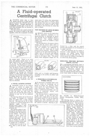
ACLUTCH which slips at slow speeds and •drives at high speed is shown in patent No. 652,527, by L. De Dionigi, Rome. Though described as a-hydraulic variable gear, it can be seen from. first principles that no increase in torque can occur.
" The unit consists of a multi-cylindered pump, the casing of which is the input member, whilst the crankshaft (1) forms the output shaft. There is no valve gear; the pistons merely draw in and expel liquid from their working spaces 12), so that at slow speed no drive is transmitted. The fluid path is restricted by ports (3), so that as the engine speed rises, the fluid is unable to pass through in the limited time available and some power is then transmitted. The effect is heightened by making the restriction smaller at high speed; this is brought about by the outward centrifugal action of sliding sleeves (4), which limit and finally close off the ports. At high speed a complete hydraulic lock can thus be obtained.
A NOVEL JACKING SYSTEM
A JACKING system of the built-in type is shown in patent No. 652,379, which comes from H. Jezler. Zurich, Switzerland. The novel feature is that the jacks not only raise the vehicle, but can also be used to move it sideways to get out of an awkward position. The drawing shows one of the set of four jacks. It consists of a screwed shaft (I) fitted with a large circular foot (2). The jack can be set to slope as shown, or it can be swung over to the opposite angle, being
pivoted about point 3 and remotely controlled by a set of levers (4).
The jacking action it performed by an electric motor (5) driven from the batteries of the vehicle. The motor rotates a worm wheel (6) which is also a nut on the screwed jack-shaft. As the nut is turned, the shaft is held by a'friction clutch and a normal lift is obtained.
If the screw be run to its limit, that is, until an abut ment piece (7) strikes the wormwhecl, the screw then starts to revolve, when the circular foot acts as a road wheel and moves the vehicle to left or right according to the direction in which the jack is sloped.
NEW METHOD OF USING RUBBER FOR SPRINGS
ADEVICE which can be tised either for suspension members or for shock-absorbers is disclosed, in patent No. 652,266, by H. Neidhart, Geneva, Swit*land. The scheme employs rubber rods which are loaded in radial compression.
The drawing shows the square tubular casing, and the square inner .shaft to which the loading arm (1) is attached. The two members are sepgrated by rubber rods (2), which are of round section before assembly. When loaded, as shown in the right-hand drawing, the rubber rods are distorted, and undergo both a change of shape and a rolling action in the square tube. The patent shows other polygonal shapes for the tubes, such as triangles and hexagons, according to the number of rubber rods requIred.
A PEDESTRIAN-CONTROLLED WORKS TRUCK
AN' electrically' propelled hand truck for works or warehouse use is shown in patent No. 651,476, which comes from the Lewis-Shepard Company, Watertown, Mass., U.S.A. The truck is pedestrian-controlled, and the patent. is concerned mainly with the methods of control.
The drawing shows a general layout of the vehicle. It has two free rear wheels, and a single driver at the front. The electric motor (1) and its reduction gearing are both mounted over the single aheel, and swivel therewith when the whicIe •is steered. Steering is per formed by a tiller, and the control buttons and switches are all mounted on its upper end (2).
The load platform can be raised or lowered a short distance for loading purposes, the lifting means being hydraulic rams (3) and links (4). The motive power for lifting is provided by an electrically driven pump.
REDUCING FRICTION BETWEEN SPRING LEAVES
1N a conventional leaf-spring, there is a considerable rubbing action between adjacent leaves, and if they are not adequately lubricated, squeaks and
harshness of action may arise. An insert for placing between the leaves to avoid these faults is shown in patent No. 652,269, by Willys-Overland Motors Incorporated, Toledo, Ohio, U.S.A.
The drawing shows a section of a spring assembly with the inserts in position between the leaves. The leaves are curved on one side, and the inserts are correspondingly shaped, being thicker at their edges. The material is fibrous paper, with stitchedon strips at the edges, the whole being impregnated with a mixture of paraffinwax and stearic acid. This mixture, known as silenitc, has the property of lubricating without at the same time having any tendency to squeeie out: The shape accorded the inserts prevents them from moving laterally.