


Suspension System Having Air as Resilient Medium
Page 32
If you've noticed an error in this article please click here to report it so we can fix it.
FROM Firestone Tire and Rubber Co., Ltd., Great West Road, Brentford, comes
patent No. 519,877 describing a novel suspension system.
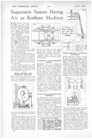
This scheme, intended for lorries, employs air, trapped in a rubber bellows, as the • resilient medium.
The axle casing carries a pair of brackets (1) which extend longitudinally and outwardly to the underside of the bells (2). The bellows are positioned as far outside the frame as practicable in order to ensure lateral sta bility. Each bellows is 'piped to its own air reservoir (7), a valve being incorporated to give rapid deflec tion but slow rebound. •
To deal with the torque reactions, a link system is employed; this consists of rubber-bushed collars (6) around the axle, ,pivotally coupled by vertical Varms (4) to a double pivot (5). Lateral stability is assisted by the provision of links (3) attached to the axle casing by a ball-joint.
Another scheme is shown in which only one pair of bellows is used; this is located behind the axle, the front ends of the brackets (I) being attached to the frame by a shackle.
NOVEL CONTROL FOR HYDRAULIC COUPLINGS -ro vary the vane angle, and so control the conversion ratio, is the object of a modification to the design of hydraulic coupling of the Fiittinger
type shown in patent No. 519,968 by A. Oliver, 8, Portland Street, Leamington Spa.
The drawing depicts a device of this type with the usual driving vanes (3) carried in the rotating casing, and the driven vanes (5) mounted upon the output member. The patent covers the use of small pivoted vanes (2) the • angle of which can be varied by crank'shafts (1) operated by push-rods (4) 'frotn outside. In one extreme position, the additional vanes (2) form continua tions of the driving vanes (3), whilst in the other extreme (90 degrees rotated) they completely close off the fluid path and terminate -the drive.
Another scheme shows the vanes adjusted_ by racks and pinions instead of crankshafts.
A .PUSH-PULL VALVE-OPERATION SCHEME INTEREST seems to be growing in schemes for the positive actuation of valves in both directions, and patent No. 519,914 shows a scheme of this nature. The patentee is A. Wattel, 2 rue des Mureaux Gris, Sevres, France. An accompanying drawing shows the scheme applied to overhead valves.
A grooved cam (3) is used in which a roller-ended push-rod works. The push-rod is positioned by being mounted upon an arm rocking about the pivot (4). The valve is operated by a rocker (2) which has a forked end embracing a grooved stirrup (5) attached to the valve-stem by split collars. A spring (6) provides a slight resilience in the closing direction, whilst working clearance can be adjusted by the setscrew (I).
BRAKE SHOES PRODUCED FROM PRESSINGS
1-1 A BRAKE shoe formed from welded
steel pressings forms the subject of patent No. 519,969 by Bendix, Ltd., and G. Roberts, both of King's Road, Tyseley, Birmingham. A section of an assembled shoe is illustrated.
This consists of two symmetrical parts each formed with a circular face ( 1) and an inwardly extending flange (9). At several points, dimples (3) are formed for the purpose of uniting the halves by welding. The periphery is slit at a number of points and the
POWER-OPERATED HYDRAULIC STABILIZER
FOR countering the effect of centrifugal force when cornering, a device is shown in patent No. 518,848, by Dr. Muller, Rumannstrasse 29, Hanover, Germany. The scheme functions by causing the body to tilt in the opposite direction to that caused by cornering.
The drawing shows, on different scales, the chassis attachment and the control mechanism. The former comprises a pair of hydraulic cylinders (1 and 2) which, when subjected to liquid pressure, tends to lift the body on its springs. The control mechanism corn
prises an engine-driven pump (9) which normally circulates liquid around a closed circuit within the device.
A slide-valve (3) is coupled to a hanging pendulum (6) so that cornering causes the slide valve to be moved either up or down, according to the direction of turning. The valve then diverts the pumped liquid to one or the other of the hydraulic cylinders, causing the body to be tilted to an angle sufficient to nullify the action of centrifugal force. A spring-loaded plunger (5) in the fluid circuit acts as a shock absorber while the load is being supported by the hydraulic system.