


Patents Completed.
Page 20
If you've noticed an error in this article please click here to report it so we can fix it.
Complete specifications of the following patents will be sent to any address in the United Kingdom upon receipt of eightpence per copy at the Sale Branch, Patent Office, Holborn,
TIPPING WAGON. — Wild. — No. 15,778, dated 1st July, 1910.—According to this invention the chassis of the wagon is provided with two rails, preferably of channel section, which extend for the greater part of the length of the chassis and also beyond the rear end with a downward curve. The wagon body is carried upon wheels or rollers on these rails, and is provided with a toothed rack on its underside. Engaging with this toothed rack is a pinion which is driven through a suitable clutch from the shaft transmitting the drive to the road wheels. When it is desired to tip the wagon, this clutch is put into engagement and the platform or body is carried along the rails, and, owing to the downward curve at the rear end, the wagon is tipped to any required degree. It is brought back again by reversing the drive on the shaft and the direction of rotation of the pinion engaging the rack.
RELIEF VALVE.—Davidson.—No. 15,588, dated 29th June, 1910.—In this specification there is described a relief
valve for a condensing steam engine which will not only drain the water from the cylinder in the ordinary way, but will also relieve excessive pressure in the cylinder due to compression should the engine have to run under non-condensing conditions. There is fitted in the cylinder casting a valve acting as an ordinary drain valve, and this is held on its seat by a spring which has a pressure somewhat in excess of the boiler pressure. When this valve opens condensed water can pass from the cylinder to the exhaust. In alignment with this valve there is a second valve bearing against the drain-valve spring and held on its seat by a weak spring giving only a pressure of 3 or 4 lb. per square inch. Under
ordinary working conditions the back of this second valve is open to the steam chest and on account of its larger area it will be held to its seat with a greater pressure than can be exerted by the drain-valve spring. When starting up the steam is cut off from the back of the second valve so that the first valve is opened by very slight pressure_ As soon as the compression pressure overcomes the pressure of the drain-valve spring, the drain valve is opened and permits the port in connection therewith to fill with steam at high pressure; it then acts upon the interior of the second valve and brings the same almost into equilibrium.
TAXIMETER.—Rogers. — No. 8,824, dated 14th November, 1910.—In the usual construction of taximeters and of similar indicating apparatus, the indicating dials are so mounted as to be capable of being brought to zero from any position. This has hitherto been accomplished by means of heart-shaped cams each of which is engaged by a lever having a point that enters the notch between the lobes, and thus causes the shaft to occupy the zero position. It is found that, unless the mechanism be very light, rapid operation of the gear is not possible owing to the inertia of the moving parts causing the zero position to be passed. According to the present invention, the levers are arranged in scissors fashion, and they have their outer ends connected by a spring in tension. When the inner ends of the levers are brought together to zeroize the dials, the outer ends simultaneously approach one another, and the tension on the spring is reduced so that the force causing the returning motion of the dials diminishes as they approach the zero position.
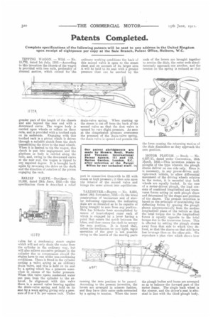
MOTOR PLOUGH. — Stock. — No. 4,937/11, dated under Convention, 16th March, 1910.—This invention relates to ploughs of the type wherein the plough shares deliver on one side only. Since it is necessary, in any power-driven multiple-track vehicle, to allow differential movement of the driving wheels relative to the motor, it is essential that both wheels are equally loaded. In the case of a motor-driven plough, the load consists of combined longitudinal and transverse forces acting on each plough share and determined by the shape and position of the shares. The present invention is based on the principle of neutralizing the deflecting forces by spacing the plough shares unsymmetrically from the median longitudinal plane of the vehicle so that the total torque due to the longitudinal forces is equally opposite to the total torque due to the transverse forces. This is effected by setting the plough shares away from that side to which they deliver, so that the shares on that side have less leverage than on the other aide. We reproduce a plan view which shows how the plough bodies and frame are arranged so as to balance the forward part of the motor frame. The single back wheel is the steerer, and the driver's seat is situated in line with the third plough body.