


AN INGENIOUS ROTARY ENGINE.
Page 28
If you've noticed an error in this article please click here to report it so we can fix it.
A Résumé of Recently Published Patents
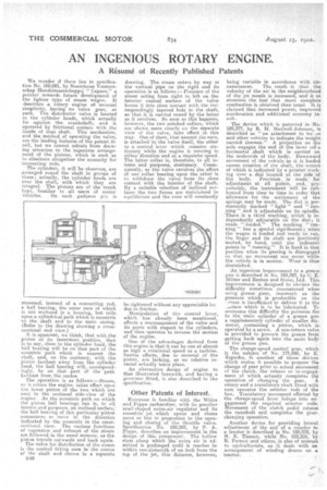
We wonder if there lies in specification No. 169,681, by Naamlooze -VennoOtschap Handelmaatschappij " Capaso," a pointer towards future development of the lighter type of steam wagon. It describes a rotary engine ofi unusual simplicity, having no valve gear, as such. The distributor valve is located in the cylinder heads, which actually lie against the crankshaft; and is operated by frictional contact with the inside of that shaft. This mechanism, and the method of operating the valve, are the leading features of the patent itself, but we cannot refrain from drawing attention to the ingenious arrangement of the pistons, which is such as to eliminate altogether the necessity for connecting rods:
The cylinders, it will he observea, are arranged round the shaft in groups of three; actually, the cylinder heads are near the shaft, with which they era integral. The pistons are of the trunk type, familiar to all users of motor vehicles. On each gudgeon pin is mounted, instead of a connecting rod, a ball bearing, the outer race of which is not enclosed in a housing, but rolls upon a cylindrical path which is eccentric to the shaft and to the main casing. (Refer to the drawing showing a crosssectional end view.)
It is apparent, we think, that with-the piston at its innermost position, that is to say, close to the cylinder head, the ball bearing will be on that part of the eccentric path which is nearest the shaft, and, on the contrary, with the piston farthest away from the cylinder head, the ball bearing will, correspondingly, be on that part of the path farthest from the centre.
The operation is as follows —t earn, as it enters the engine, takes effect upon the lower piston of the two which are seen in the sectional side-view of the engine. As the eccentric path on which the piston ball bearings run is, to all intents and purposes, an inclined surface; the ball bearing of this particular piston commences to move in the direction indicated by the eccentric in the crosssectional view. The various functions of expansion and exhaust of the steam are followed in the usual manner, as the piston travels outwards and back again.
The valve for distribution of the steam is the conical fitting seen in the centre of the shaft and shown in a separate Ls16 drawing. The steam enters by way or the vertical pipe on .the right and its operation is as follows :—Pressure of the steam acting from, right to left on the interior conical surface of the Valve forces it into close contact with the correspondingly tapered hole in the shaft, so that it is carried round by the latter as it revolves. So soon as this happens, however, the two notched collars, which are shown more clearly en the separate view of the valve, take effect in. this way. One of them, that nearest the nuts, is attached to the valve itself, the other to a control lever which remains stationary while the engine is running in either direction and at. a iequisite speed. The latter collar is, therefore, to all intents and purposes, stationary. Consequently, as the valve revolves the effect of one collar bearing upon the other is to withdraw the valve from its close contact with the interior of. the shaft. By a suitable eelection of inclined surfaces the two forces are maintained in equilibrium and the cone will constantly be tightened without any appreciable lot due to friction.
Manipulation of tha control lever, which has already been mentioned, effects a rearrangement of the valve and its ports with respect to the cylinders, and thus operates to reverse the motion of the engine.
One of the advantages derived from this engine is that it can be rim at almost as high a rotational speed as a turbine. Inertia effects, due to reversal of the piston, are lacking, as no relative reversal actually takes place.
An alternative design of engine to that illustrated herewith, and having a governor fitted, is also described in the specification.
Other Patents of Interest..
Everyone is familiar with the White and Poppe carburetter, with its peculiar snail shaped extra-air regulator and its eccentricjet which opens and closes more or less in proportion to the opening and closing of the throttle valve. Specification No. 182,281, by P. A. Poppe, describes an improvement in the design of this component. The hollow stem along which the extra air is admitted is prolonged until it reaches to within one-sixteenth of an inch from the top of the jet, this distance, however,
being variable in accordance with eir
-cumstances. The result is that the velocity of the air in the neighbourhood of the jet nozzle is increased, and it so atomizes the fuel that more complete combustion Is obtained than usual. It is claimed that increased power, improved acceleration and additional economy result.
The device which is patented in No. 182,377, by R. M. Maxwell-Johnson, is described as " an attachment to for .es and other vehicles to indicate the weight ,carried thereon." A projection on the axle engages the end of the lever on a .horizontal shaft which is carried on the underside of the body. Downward movement of the vehicle as it is loaded causes rotation of the shaft; the' extent of which is indicated by a pointer working over a dial located at the side of the body. Provision is made for 'adjustment it all pOinte, and, preSinnably, the instrument will be calibrated frum time to time in order that allowance' for the settlement of the springs may be made. The dial is permanently marked " light " and "running " and is adjustable on its spindle. There is a third marking, which is independently adjustable on the dial; it reads "loaded." The marking " running " has a special significance; when the wagon is loaded and ready to run, the finger and its shaft are positively indicator
points by hand, until the points to ' running:" It is fixed in that position when its gearing is disengaged so that no movement can occur while the vehicle is in motion. Wear is thus diminished.
An ingenious improvement to a grease gun.is described in No. 182,387, by C. E. Milner and Benton and Stone, Ltd. This improvement is designed to obviate the difficulty sometimes encountered when using grease guns, inasmuch as the pressure which is producible on the ease is insufficient te deliver it to the .griace which is to be lubricated. To overcome this difficulty tha patentee fits to the swain cylinder of a grease gun a supplementary cylinder of smaller diameter, containing a. piston, which is operated' by a screw. A non-return valve is provided to prevent the grease from getting back again into the mails body of the grease gun:
The change-speed control gear, which is thesubject of No. 171,095, by E. Zaparka, is another of those devices which makes it possible to prepare the change of gear prior to actual movement of the clutch, the release or -re-engagement of which actually completes the operation of changing the gear. A rotary and a transl-atory shaft fitted with cam operates the selector rods of the box. Tratislatory movement effected by the change-speed lever brings into engagement the required selector rods. Movement of the clutch pedal rotates the camshaft and, completes the gearchanging operation.
Another device, for providing lateral adjustment of the end of a coupler to a tractor is described in No. 182,239, by H. E. Timmis, while No. 182,225, by R. Ferrnor and others, is also of interest to agriculturists, as it deals with an arrangement of winding drums on a
tractor. .