


PATENTS SUMMARIZED.
Page 22
If you've noticed an error in this article please click here to report it so we can fix it.
Interesting Spring Suspension,
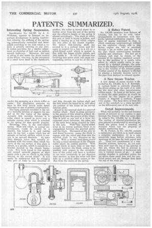
SpecificaVion No. 116,737, by A. C. 'Wickman., appears to forecast , an important development in spring construction whereby the stiffness of the springing, automatically controlled and determined according to the load which a vehicle is actually carrying at any Jime. R1 makes provision for a similar adjustment on stretches of bad road as against smooth highways. • Moreover, the -ease of riding is also under the direct control of the driver, who may, by the movement of a small lever fixed to the dashboard, render the springing as a whole stiffer or easier. For descriptive purposes -we have in this brief article made detail reference to one of several constructions.
The basic principle involved, is the use of a movable fulcrum or support for one end or for the centre of the spring. Actually this movable fulcrum is a roller which is caused to move over a suitable convex plate which is attached to the spring for that specific purpose. Referring,then, to the semi-elliptic spring. That end which, in normal circumstances, would be carried by a shackle, has bolted to it, and resting upon its top leaf, a plate which has an arcuate, or curved, surface, which is convex in ate upward direction. At some little distance below this, actually coincident with the centre fpom which the curve of the Lop surface of this plate is struck, is a spindle, which is carried by a bracket secured to the chassis framework. Two links keyed to this spindle and carried upwards ,support at their upper ends a pin on which is the roller bearing on the curved plate!' . It will easily be understood that by swinging this pair of links in one direction or
a lather, the roller is moved closer to or further away from the end of the spring and the effective length of the spring is altered accordingly. The shaft to which this pair of !inks is keyed is hollow, and takes a bearing on a rod which couples the two sides of the chassis together. The hollow link-carrying shaft has secured to it a vertical lever, and this again is coupled by a link to a nut on a quick-thread screw which is carried in line with the frame, of tthe .vehicle and just inside it. It will be obvious that revolving this screw shaft will cause cotresponding motion to and fro of the nut,
and this, through the hollow shaft and the link which are keyed to it, will affect the position of the roller on its curve0 fulcrum plate.
Keyed to the screwed shaft is a grooved friction wheel. Rem in iclose proximity to the groove of this wheel is a block designed to'fit'inta the groove of the wheel. This is held on one end of a lever felcrummed' about itskcentrre, the other end of the same lever being coupled by links to the axle. With9his double-ended lever in its central position,' there is no engagement between the grooved pulley and the block. Movement of the axle up and down;'however, causes the block to engage with the wheel and thus turn the screwed shaft in one direction or the other. With a normal loatIl.there&would be only a small movement of the fulcrum roller -about its central position. With a load which is more than or less than normal, however, the block, owing to its position with respect to the circumference of the pulley will have a tendency to act more intensively in one direction than another, so that the roller will thus take up a position either nearer,or farther from the centre of the spring.
A Robey Patent.
No. 116,985 emanates from Itobeys, of Lincoln, and bars to do with valve arrangements in connection With twostroke internal-combustion engines. The type of engine concerned is that in which crankcase compression Os utilized for the explosive charge, and in this Robey engine the fuel is admitted through a jet or orifice near the top of the pipe which communicates between cylinder and crankcase. The fuel jet is vertical, and may be closed, or the amount of its opening regulated according to the position of a needle valve abeve it, which needle valve is supported by, a dashpot plunger, the pressure in the dashpot being reduced according to the velocity of the exhaust.gases. Further control of the dashpot is effected by placing a butterfly throttle valve in the pipe from dashpot to exhaust' ejector.
A New Steam Tractor.
A new design of steam tractor is ,deselibed'in No. 116,855, by J. F. Ridealgh. A vertical boiler is centrally disposed, the driver sitting on the right of it, with the fire door and other appurtenances within reach. In front of the boiler, and in about the same position as would be occupied by the engine of a petrol chassis, is disposed a vertical, V-type twin engine. The final drive is from the end of the camshaft to a chain sprocket on the differential case of the rear axle.
Detail Improvements.
What will -probably be film last German patent of interest to our readers to pass through the Patent Office for some time to con-.erie No. 116,824, by A. Riedlor. The cooling of internal-con-,bustion engine pistons is accelerated by securing beneath the piston head a quantity of material which has the property of rapidly conducting heat.
W. R. Parker, in No. 116,792, patents a carburettor jet which is in itself almost a complete carburetter. It is a comparatively large hollow structure with apertures at,its base for both petrol and
These two constituents of a combustible mixture, however, do not 'combine until nearthe top of the interior of this' jet, where the fuel' is allowed to emerge from a number of horizontal jets into a vertical stream of air. 'A small mixing chamber is embodied within the jet above these small jets, and the cow.biped petrol and air emerges then from the top of the mainjet.