


Patents Completed.
Page 24
If you've noticed an error in this article please click here to report it so we can fix it.
ANTI-SLIP DEVICE. -BuggL — No. 27,811, dated 6th December, 1906.--Two dished members (D) are placed back to
back, and secured together by internal members (DC, D4) and a bolt M. This device is carried by links at the rear of the vehicle, and a spring (L) tends to force it into contact with the ground. A chain,
or other device, is provided for lifting it -from the ground when it is not required to be operative.
ANTI-SLIP DEVICE.—Wheatcreft.— No. 25,060, dated 7th November, l906.Rollers (A) are pivoted by links (13) to the rear axle of the vehicle. The rollers lie between the two rear road wheels, and arc connected by toggle links (F) to a 'vertical rod (G). This rod is connected by a lever (g) with operating mechanism so that, when the lever is moved to raise the toggle links, the rollers ,..re drawn towards each other, and are thus made to bear against the road surface. The vertical member (G) is connected with a valve (J) within a sand chamber, and conduits 1.6) extend from this chamber towards the road wheels. It thus follows that, when the anti-slip device is applied, sand is also discharged in proximity to the road wheels. The links (B) and the rollers (A) are pivoted to vertical spindles carried in bearings (d) on the axle, and, on the -upper ends of these spindles, wheels (C) are mounted. A chain (0) connects the wheels (C) with the steering gear, whereby the rollers (A) are made to turn with the steering wheels.
MOTOR VEHICLE.—Hele-Shaw.. No. 15,463, dated 7th July, 1906.– -The vehicle is propelled by feet (1)1 carried
in rotatable tables (B). Each table is conveniently driven by a worm and worm wheel, and the feet are so mounted that they can slide vertically within the tables. At the top of each foot is a roller, and above the feet is a cam member (E, El) whereby each foot, in turn, is depressed, as the tables rotate, to bring them successively into contact with the road surface. The feet are conveniently carried on trunnions D2 in the tables, and are depressed to bring them into contact with the ground against the action of a spring mounted within each foot. It thus follows that, as each foot arrives opposite the lowest point of the cam, it is brought into contact with the ground, but, as soon as it leaves this part of the cam, it is again lifted therefrom. Each cam can be turned about the same centre as the table appropriated thereto, and it will be seen that, when the cams are so set that the feet furthest from the centre line of the vehicle are made to bear upon the ground, the vehicle will travel straight forward,
but, as the cams are turned, the feet will be made to come into contact with the ground at different points relatively to the centre line of thevehicle, and, as each foot is travelling in a circular path, the vehicle may thus be made to travel in any direction.
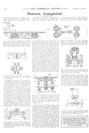
SCAVENGER STROKE.—Slinm—No. 16,524, dated 21st July, 1906.—The work. Mg piston (In is rotatably connected to a divided crank (d) and it is made hollow. in the working end of the piston is a valve (m), and the other end is closed by an adjustable head (g). The piston (h) is rotated by bevelled gearing (c), one of the wheels being carried by the crank (d1. In the piston is a port (e) adapted to register with air inlet and mixture inlet ports in the wall of the cylinder. During the working stroke, a charge of air previously drawn into the piston (b) is compressed, by reason of the piston travelling over the head (g), and, when the exhaust valve (a) opens, this air passes into the combustion space by way of the valve ins) and
scavenges the cylinder. During the return stroke of the piston, the scavenging air is driven out of the cylinder, and a charge of mixture is drawn into the piston.. The next out-stroke compresses the charge in the piston, and this is discharged through the valve into the cylin der to be compressed on the following return stroke and to constitute the explosive charge of the next out-stroke.
STEERING GEAR. — Bingley. — No. 26,451, dated 22nd November, 1906.--The axle (A) of the front wheels (0) is pivoted on a vertical pin (1'). The vehicle also engages this pin, and rests upon a spring (L) on the axle. A rearwardly projecting arm (II) is secured to the axle and on the arm is a toothed quadrant (H). A pinion (I) which meshes with this quadrant is
mounted on the steering-wheel shaft. Steering is thus effected by turning the axle (A) bodily about the pin (I").