


Unusual Features in a
Page 54
If you've noticed an error in this article please click here to report it so we can fix it.
New Morris-Commercial
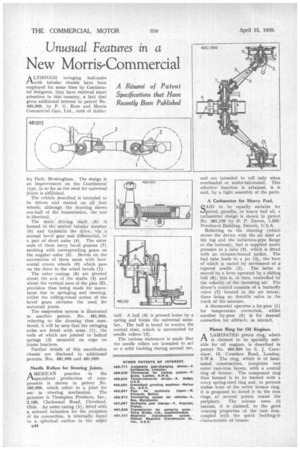
A LTIIOUGH swinging half-axles tAwith tubular chassis have been employed for some time by Continental designers, they have received scant attention in this country, a fact that gives additional interest to patent No. 480,969, by P. G. Rose and Morris Commercial Cars. Ltd., both of Adder
ley Park, Birmingham. The design is an improvement on the Continental type, in so far as the need for universal joints is abtlished.
The vehicle described is intended to be driven and steered on all four wheels; although the drawing shows one-half of the transmission, the rest is identical.
The main driving shaft (5) is housed in the central tubular member (6) and transmits the drive, via, a normal bevel gear and differential, to a pair of short axles (4). The outer ends of these carry bevel pinions (7) meshing with corresponding gears on the angular axles (3). Bevels on the extremities of these mesh with horizontal crown wheels (9) which pass on the drive to the wheel bevels (1).
The outer casings (8) are pivoted about the aa:is of the shafts (4) and about the vertical axes of the pins (2), provision thus being made for movement due to springing and steering, whilst the rolling-round action of the bevel gears obviates the need. for universal joints.
The suspension system is illustrated in another patent, No. 481,005; referring to the drawing thus numbered, it will be seen' that the swinging axles are fitted with arms (1), the ends of which are jointed to helical springs (2) mounted on cups on frame brackets.
Further details of this unorthodox chassis are disclosed in additional patents, Nos. 481,006 and 481,009.
Needle Rollers for Steering Joints. A MERICAN practice in the .1-1.specialized production of components is shown in patent No. 480,990, which refers to a joint for use in steering mechanism. The patentee is Thompson Products, Inc., 2,196, Clarkwood Road, Cleveland. Ohio. An outer casing (1), fitted with a screwed extension for the reception of its connection, is internally bored to a spherical outline in the upper
B49 half. A ball (3) is pressed home by a spring and forms the universal member. The ball is bored to receive the central stud, which is surrounded by needle rollers (2). The curious statement is made that the needle rollers are intended to act as a solid bushing during normal use, and are intended to roll only when overloaded or under-lubricated. This selective function is attained, it is said, by a tight assembly of the parts.
A Carburetter for Heavy Fuel.
SAID to be equally suitable for petrol, paraffin, or heavy fuel oil, a carburetter design is shown in patent No. 481,139 by B. P. Dawes, 1,550, Penobscot Building, Detroit, U.S.A.
Referring to the drawing (which shows the device with the air inlet at the top and the induction-pipe flange at the bottom), fuel is supplied tinder pressure to a tube (3). which is fitted with an exhaust-heated jacket. The fuel tube leads to a jet (4), the bore of which is varied by movement of a tapered needle (2). The latter is moved by .a lever operated by a sliding bell (6); this is, in turn, controlled by the velocity of the incoming air. The driver's control consists of a butterfly valve (7) located in the air intake, there being no throttle valve in the track of the mixture.
A thermostat operates a by-pass (I) for temperature correction, whilst another by-pass (5) is for manual correction for altitude, in aircraft.
Piston Ring for Oil Engines.
ALAMINATED piston ring, which is claimed to be specially suitable for oil engines, is described in patent No. 480,860 by S. J. Crawthaw, 15, Crondace Road, London, S.W.6. The ring, which is of laminated construction, comprises two outer cast-iron layers. with a central ring of bronze. The compound ring thus formed is to be backed with a wavy spring-steel ring and, to prevent undue wear of the softer bronze ring, it is proposed to dowel it to the iron rings at several points round the periphery. The scheme owes ith success, it is claimed, to the good wearing properties of the cast iron, coupled with the quick bedding-in characteristic of bronze.