


CONVERTING A STANDARD CHASSIS TO A FIRE PUMP.
Page 11
Page 12
If you've noticed an error in this article please click here to report it so we can fix it.
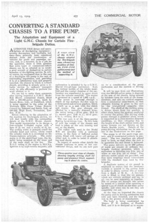
The Adaptation and Equipment of a Light G.M.C. Chassis for Certain Fire.
brigade Duties.
AO UGH THE design and mann
facture of fire-fighting equipment— notably fire-engines and turntable ladders—have generally been considered distinct from the construction of vehicles for goods and passenger service, and, in a measure, to be a job the the specialist, there is little question that some types of commercial-vehicle chassis can be so adapted" as to render a good account of thremaelves in certain Branches of fire:fighting service. It will, of course, be recogmzed that in the case of a fire-engine the pump is the unit of outstanding importance, and, providing it of a. satisfactory type and properly installed, the chassis to which it is fitted should, providing it already gives a reliable service in ordinary transport work, be able efficiently to perform the work allotted to it.
We are led to make these comments alter having inspected a G.M.C. Model K16 30-cwt. commercial chassis, fitted with a 200-250-gallon pump, made by Ilennis Bros., Ltd., of Guildford, which is being supplied to the order of the Waltham Holy Cross Urban District Council by Tankard and Snail, Ltd:, of 226-2321 High Road, Tottenham, London, N.16,
Before referring to the adaptation of the machine for fire-brigade service, we will deal briefly with the o-utatanding details of the G.M.C. 30-cwt. chassis. This model ineorporates in its design a four-cylinder L-headed engine with a' bore of 31 ins, arid a •stroke of 51 ins. The cooling Water is pUmned round the cylinder head arid valves, whilst round the cylinder walla it is Circulated on the thermo-siphonic principle. The water pump is of the centrifugal type, the peller being mounted on the innerend of the same shaft as the fan. • The R.A.C. -rating of the engine is 11.6 h.p. Ignition is by high-tension Magneto,and carburation is attended to by a G.-M.C. Marvel 'two-jet-type instrument. Both the vertical Section of the intake manifold and the venturi chamber of the carburetter are superheated by gases direct from the exhaust manifold. -The engine is governed at aaspeed of 1,445 ap.m. The power is conveyed through a clutch of the multiple dry-diet type. to a three-speed-and-reverse gearbox, which is built up as a unit with the clutch and engine. The gear .changes are effected by a centrally disposed lever, the ratios being a--First gear, 21.9 to 1; second ge:Ar, 9.48 to 1; third gear, 6 to 1; reverse, 26.6 to 1,
The rear axle is of the three-quarter floating bevel-driven type. in this forth of axle the weight of the chassis and load is taken on the axle housing and not on the shafts.
The radius rods used. in the Model K16 are provided with a universal action, in the form of hall-and socket joints, fitted with heavy coil springs at either end, in order to assist in absorbing toad shocks In respect of certain other details the chassis conforms to snore or less convefitional design, and we can now pass on to a consideration of the _pump mechanism and the method of driving it.
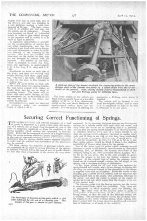
It will he seen from our illuatrations that the. 200-250-gallon pump is disposed at the rear of the chassis, being secured by brackets front the ends of the framemembers, and also on vertical supports from a substantial cross-bearer, so that adequate bracing is given to the unit by the triangulated supports thus fermed. The shaft-uf the turbine pump is driven direct from the gearbox, a silent chain being the medium employed to convey the power. The driving shaft passes through a plummer block which is supported on a cross-member disposed amidships, so that. whipping aue to the length of the shaft cannot occur, and severe stresses are not thrown on the Hardy flexible joints. Detaila of the pump-driving mechanism can he seen in one of the illustrations on this page. ;The pump is of the multi-stage pattern, and is. constructed entirely in gunmetal. The two impellers are placed back to back, so that when the unit is in operation the end •thrust is balanced.
The pump delivers up to 250 gallons of water per minute at ordinary firebrigade working pressures, which is equivalent to throwing two 2-4n. jets of water or one jet of water. Two delivery outlet valves are provided, and. they have couplings which interconnect with the standard type used by firebrigades. A duplicate system of air purniA is employed to ensure that the necessary vacuum is created in the suction hose in order to obtain vertical lifts of water from a depth of 26 ft. A two-way cock is fitted so that the air pumps, which are entirely enclosed and run in oil, can be used separately or together. The air pumps are brought, into action by means of a control lever operating a special type of clutch on the main pump spindle, and when not in iise they are completely cut out.
At the time we inspected the chassis the pump and its driving mechanism had only just been installed, and the body was in the process .of manufacture.
The body is being constructed hat Messrs. P. W. Jenkins, of Ponders End, and it ia so designed as to accom33I1 modate four men on each side, two On the' driver's seat and two standing on a rear platform, making a total complement of 12 men. The body frameevork • is of selected ash and oak, and the panels are of mahogany. Forged: iron brackets are fitted at vulnerable'.: Points in order to give added strength to the structure and to enable it to be' made as light as possible. A capacious compartment is provided foe the accommodation of suction hose -and other impedimenta, and the lids enclosing it are fitted with strong hinges, and open downwards in order to facilitate removal of the contents of the interior. The doors are panelled with sheet-steel on the inside, so that they are not damaged by contact with the contents. The interior of thebody, which is designed to carry, the hose, _tools and appliances, is approximately 6 ft. 6 ins. long, 3 ft. deep and 3 ft. wide.
Footlioards are fitted on each side of the body, and these are covered with rubber matting with stout angle beading. The top of the body, which forms a seat for the men, is also treated in a similar way.
Boxes are to be fitted on each side' of the vehicle below the running boards, the tops being covered with rubber to render there safe for use as steps or mounting boards. The boxes will be fitted with quick-action fittings 60 that the standpests, 'etc., to be housed on one side and the tools on the other, can readily be removed.
Arrangements are made for darrying an extension ladder, the maximum length of which is 34 ft. The front wheels of the vehicle are fitted with pneumatic tvres.of a non-skid pattern of 34 in. by in. dimensions, whilst on the rear wheels Goodyear allweather-tread cushion tyres are emPloyed. For the purpose of inflating the
pneumatics a Kellogg. power pump is installed.
The vehicle will be finished in the usual fire-brigade colours, and so seen as it is completed we hope to be Ate to Illustrate it in our pages. •