 1
1 2
2 3
3 4
4 5
5 6
6 7
7 8
8 9
9 10
10 11
11 12
12 13
13 14
14 15
15 16
16 17
17 18
18 19
19 20
20 21
21 22
22 23
23 24
24 25
25 26
26 27
27 28
28 29
29 30
30 31
31 32
32 33
33 34
34 35
35 36
36 37
37 38
38 39
39 40
40 41
41 42
42 43
43 44
44 45
45 46
46 47
47 48
48 49
49 50
50 51
51 52
52 53
53 54
54 55
55 56
56 57
57 58
58 59
59 60
60 61
61 62
62 63
63 64
64 65
65 66
66 67
67 68
68 69
69 70
70 71
71 72
72 73
73 74
74 75
75 76
76 77
77 78
78 79
79 80
80 81
81 82
82 83
83 84
84 85
85 86
86 87
87 88
88 89
89 90
90 91
91 92
92 93
93 94
94 95
95 96
96 97
97 98
98 99
99 100
100 101
101 102
102 103
103 104
104 105
105 106
106 107
107 108
108 109
109 110
110 111
111 112
112 113
113 114
114 115
115 116
116 117
117 118
118 119
119 120
120 121
121 122
122 123
123 124
124 125
125 126
126 127
127 128
128 129
129 130
130 131
131 132
132 133
133 134
134 135
135 136
136 137
137 138
138 139
139 140
140 141
141 142
142 143
143 144
144 145
145 146
146 147
147 148
148 149
149 150
150 151
151 152
152 153
153 154
154 155
155 156
156 157
157 158
158 159
159 160
160 161
161 162
162 163
163 164
164 165
165 166
166 167
167 168
168 169
169 170
170 171
171 172
172 173
173 174
174 175
175 176
176 177
177 178
178 179
179 180
180 181
181 182
182 183
183 184
184 185
185 186
186 187
187 188
188 189
189 190
190 191
191 192
192 193
193 194
194 195
195 196
196 197
197 198
198 199
199 200
200 201
201 202
202 203
203 204
204 205
205 206
206 207
207 208
208 209
209 210
210 211
211 212
212 213
213 214
214 215
215 216
216 217
217 218
218 219
219 220
220 221
221 222
222 223
223 224
224 225
225 226
226 227
227 228
228 229
229 230
230 231
231 232
232 233
233 234
234 235
235 236
236 237
237 238
238 239
239 240
240 Bedford's £1,775 Twin steer Passenger Chassis
Page 119
Page 120
Page 121
Page 122
If you've noticed an error in this article please click here to report it so we can fix it.
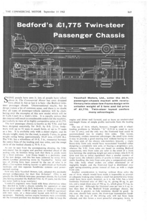
SOME people have seen it; lots a people have talked about it; The Commercial Motor has eyen dropped hints about it; but at last it is here—the Bedford twinsteer passenger chassis. Unconventional maybe, but its design makes a lot of common sense, and there is no doubt that all types of passenger-vehicle operator will be clambering over the examples of this new model which will be in Earls Court in a week's time. It is equally certain that this interest will result in considerable orders for the machine, particularly in view of its highly competitive price of £1,775.
The new passenger chassis is known as the VAL and has been designed essentially for 36=ft. by 8-ft, 2.5-in, bodywork with up to 52 seats in coach form, or up to 55 seats as a bus. It is available only with a diesel engine, and its chassis weight, ready for the road, is exactly 3 tons, its gross weight rating being approximately 10.25 tons (23,000 lb.). The VAL has a wheelbase of 19 ft. 3 in., measured between the centre lines of the leading and rear axles, and the swept circle of the bodied chassis is 70 ft. 6 in.
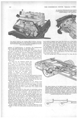
As can be seen from the accompanying drawing, the VAL twin-steerer has its engine and gearbox mounted ahead of the :eading axle, its location being such that there is ample room or a front entrance. Low frame height is a particular asset 3f the new design, and this has been achieved by using 16-in. .vheels (another pioneering move by Vauxhall's). Safely and .ase of driving have been assured by the use of what is in tffect a four-system braking layout—a split-circuit air-hydraulic lootbrake and two separate handbrake systems—and powermisted steering.
Now why have Vauxhall Motors, Ltd., adopted this decidedly tonsual configuration for their first 36-footer? (This is not ictually the first British twin-steer passenger chassis, the Leyland :inn having preceded the Bedford VAL by 25 years, but the Gnu was never built in large numbers.) Vauxhall's engineers were faced with three alternatives when hey decided to build a chassis suitable for operation at over 10 tons gross weight with 36-ft bodywork: a choice of two-axled :hassis with either 11.00-20 single tyres or 10.00-20 equipment with twin rears, or a three-axled layout with 8.25-16 (radial) :quipment. Similarly, various engine locations were considered, lut the forward position was decided upon in order to keep the
engine and driver well forward, and so leave an unobstructed low-height frame of simple profile rearwards from the leading axle.
The use of 16-in, wheels, however, brought with it wheelloading problems (a Michelin, " X " 8.25-16 is rated to carry. 1 ton 12 cwt.), and the only way the front-end load could be accommodated was to employ twin axles. This layout, fortunately, confers numerous advantages; the small tyres make it easy to provide a good steering lock without having to crank the front ends of the chassis side-members inwards; a single heavy-duty front axle would have necessitated Vauxhall either designing a completely new axle, or buying a proprietary unit, whereas the VAL front axles are based on existing Bedford components; twin front axles are safer in the event of a front tyre bursting; the unsprung weight per axle is lower; nine 8.25-16 tyres cost less as initial equipment than a smaller number of larger tyres; the vehicle's centre of gravity is lower, giving more stable handling; the twin front axles give a comparatively pitchfree ride: body wheel arches are either eliminated or of negligible height; and the front-end load is distributed over eight spring-mounting points instead of four, as with a single front axle.
Another consideration is braking: without three axles the use of 16-in, wheels would have made it impossible to providt an adequate braking area (unless a small but powerful d:sc brake could have been used), however, as it is, the VAL has a total footbrake frictional area of 504.1 sq. in., giving 49 sq. in, per ton, and a swept drum area of 794 sq. in., which gives 77.3 sq. in. swept per ton. Although the frictional area per ton is 6 sq. in. less than that of the Bedford S-type passenger chassis, the drum area is greater, so fade resistance should be 'good. In aft)/ case, should fade occur, the drum-type transmission handbrake on the nose of the driving axle will not have been affected; and this forms a most .powerful emergency brake in
addition to supplementing, if necessary, the parking-brake effect of the other handbrake on the front wheels.
So it will be seen that the design does make sense after all and there is nothing about it of which any passenger-vehicle operator need be afraid, well-tried components and principles being used throughout. Indeed, it is virtually impossible to find any serious disadvantages with the design, and its layout provides plenty of scope for body-manufacturers' ideas, the chassis being suitable for front-, centralor even rear-entrance bus or.coach bodies, whilst a left-hand-drive version is to be offered also.
So much for the thinking behind the design. Now for the actual vehicle itself. It is based on a conventional ladder-type chassis frame with 10-in. by 3-in. by 0.22-in.
channel-section side members pressed from Selected EN.2D steel and eight channelor top-hat-section cross members cold-squeeze riveted in place (the rear-engine cross member is bolted), the frame section modulus being 9.47. The off-side member is perfectly straight from front to rear, but right-hand-drive chassis have the foremost 35 in. of the left-hand member joggled in by 3.5 in. to provide clearance for an inward-opening door on a front-entrance body. Left-hand-drive chassis do not have this joggle in the corresponding right-hand member.
Both side members are swept down by 5 in. ahead of the leading axle, the flange-width reducing to 2.12 in. in the same area, whilst at the rear of the frame the lower flanges are swept upwards to reduce the depth to 6 in., the upper flanges being perfectly flat rearwards from a point some 11 in. ahead of the leading-axle centre-line.
Suspension is provided by three pairs of semi-elliptic springs which are rubber-bushed (Jkiletalastik ultra-duty) throughout to eliminate the need for lubrication. All the springs are rearshackled, and the eight front-bogie hanger brackets are of a new cantilevered type, the springs being outrigged rather than lying beneath the side members. The leading springs have seven leaves and an effective length of 50 in., the rate being 728 lb./in.
and the design load 2,615 lb. per spring. The second-axle springs have four leaves and a length of 52 in., the rate being 545 lb./in, and the design load 1,680 lb., from which it will be gathered that it is intended that the loading on the leading axle should be greater than that on the second axle.
In the unladen 'condition there is a marked difference in the attitudes of these two axles, partly because the front end of the F32
front spring is slightly lower than the front end of the secon( spring, but when laden the difference is less noticeable, and thi front axle has a castor angle of 3.5° positive, that of the secort( axle being 30 positive—the slight difference has been fount to be beneficial with regard to handling. Safety brackets an provided behind the shackles of the second-axle springs, am towards the front of the two springs on the right side, thesi being to prevent a spring fouling the steering linkages in till event of a failure. The second leaves of all the front spring are wrapped round the eyes.
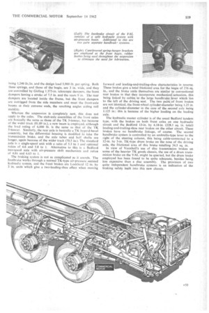
The rear springs have 10 leaves and are 67 in. long, the cab being 1,240 lb./in. and the design load 5,900 lb. per spring. Both these springs, and those of the bogie, are 3 in. wide, and they are controlled by Girling 1.375-in, telescopic dampers, the front dampers having a stroke of 7.5 in. and the rears 9 in. The rear dampers are located inside the frame, but the front dampers are outrigged from the side members and meet the front-axle beams at their extreme ends, the resulting angles aiding roll stability.
Whereas the suspension is completely new, this does not apply to the axles_ The stub-axle assemblies of the front axles are basically the same as those of the TK 5-tonner, but because of the wider track (81.89 in.), a new beam is employed, although the load rating of 6,000 lb. is the same as that of the TK 5-tonner. Similarly, the rear axle is basically a TK hypoid-bevel assembly, but the differential housing is modified to take the transmission brake, and the axle tubes and half shafts are longer, again because of the wider track (70.5 in.). The standard axle is a single-speed unit with a ratio of 5.3 to 1 and optional ratios of 4.6 and 5.8 to 1. Alternative to this is a Bedford two-speed axle with air-pressure shift mechanism and ratios of 4.86 and 6.63 to 1.
The braking system is not as complicated as it sounds. The footbrake works through a normal TK-type air-pressure assisted hydraulic system, and the front brakes are Lockheed 12 in. by 3 in. units which give a two-leading-shoe effect when moving
forward and leading-and-trailing-shoe characteristics in reverse. These brakes give a total frictional area for the bogie of 276 sq. in., and the brake units themselves are similar to conventional rear brakes in that they incorporate mechanical actuation, this being linked by cables to the large handbrake lever which lies to the left of the driving seat. The two pairs of front brakes are not identical, the front-wheel cylinder-diameter being L25 in. and the cylinder-diameter in the case of the second axle being 1.125 in.: this is because of the higher loading on the leading axle.
The hydraulic master cylinder is of the usual Bedford tandem type, with the brakes on both front axles on one hydraulic circuit and the Bedford 13-in. by 4.18-in. (228.1 sq. in. total) leading-and-trailing-shoe rear brakes on the other circuit. These brakes have no handbrake linkage, of course. The second handbrake system is controlled by an umbrella-type lever to the right of the steering column, this being cable-connected to a 124n. by 3-in. TK-type drum brake on the nose of the driving axle, the frictional area of this brake totalling 34.5 sq. in.
In view of Vauxhall's use of disc transmission brakes on some of the heavier TK goods chassis, the use of a drum transmision brake on the VAL might be queried, but the drum brake employed has been found to be quite adequate, besides being less expensive than a disc assembly. The provision of two quite independent handbrake systems is an indication of the braking safety built into this new chassis.
Burman recirculating-ball steering has been adopted for the VAL, this in itself being a departure' from previous Vauxhall practice, and the box ratio gives 5.5 turns of the 18-in.-diameter steering wheel from lock to lock, A Hydrosteer hydraulic servo, powered by an engine-driven pump, is fitted as standard, partly because without a servo the numberof turns from lock to lock would have been increased, and partly because the lightness of the steering makes the vehicle at least as easy to manceuvre as a smaller passenger vehicle, thereby removing most of the disadvantage of the extra length and width. Because basically standard front axles can be used, the fitting of a steering servo as Standard is not of particular detriment so far as cost is concerned.
The servo ram acts directly on the steering-box drop arm, a drag link also being connected from this arm to a relay lever ahead of the leading axle. This relay lever is connected to the steering arm of the leading axle and to a second relay lever the same distance ahead of the second axle, whence another drag link passes to this axle's steering arm. The layout ensures correct steering geometry to both axles, irrespective of spring deflection. Thompson sealed ball joints are employed throughout the steering linkages, so the only steering lubrication required is at two nipples on each of the four kingpins, plus three nipples on the power ram.
Whilst on the subject of grease nipples, the VAL has amazingly few for a vehicle of its size, there being only 13 all told. As just detailed there are 11 on the steering, plus one on the spline of the rearmost propeller-shaft section and one on the footbrake linkage relay lever, which passes through the chassis frame just ahead of the leading axle. Obviously this chassis is going to be an easy one to keep up to scratch.
So far no mention has been made of the VAL's power unit. This is the 400/73 Mk. 2 version of the Leyland 400-S 6.54-litre six-cylinder direct-injection diesel engine, the standard ratings of which are 125 b.h.p. (net) at 2,400 r.p.m. (for the Bedford application a governed speed of 2,600 r.p.m. has been adopted, however) and 300 lb.-ft. torque at 1,600 r.p.m. The most striking modification to this engine, when compared with the standard version as used in Leyland Group vehicles, is its cylinder head: instead of having the exhaust manifold on the right-hand side of the head, on the opposite side to the inlet manifold, the head has been redesigned so that both manifolds are on the left side, the object of this being to give more room for the driver and the controls on the right side of the engine, and also to remove the exhaust heat from that side. (Left-handdrive chassis have the standard head.)
The radiator is carried immediately ahead of the engine, protruding 4.6 in. beyond the end of the chassis frame, and the cooling system is pressurized to 7 p.s.i., a six-bladed fan pulling air through the radiator block. The air cleaner is located on the front-left corner of the engine, and a high-speed D.C. generator provides power for the 24v. electrical system, the four 6v. batteries being stowed centrally in the chassis frame about the centre-line of the bogie, with the tops of the cases pro
truding 3.5 in. above the frame top flanges. Fuel is drawn from a 26-gal. rectangular-section fuel tank which is mounted on the right-hand side member immediately. behind the rear wheels.
Another departure from conventional Vauxhall practice is the adoption of an American Clark gearbox as standard, this being a 264-VO five-speed overdrive-top unit with synchromesh engagement of the upper four ratios. The forward ratios are 6.06, 3.5, 1.8, 1 and 0.8 to 1, with reverse gearing of 6.0 to 1, and the gear lever is to the left of the driving seat, being connected to the gearbox turret by a one-piece cranked rod.
Assuming an engine governed speed of 2,600 r.p.m., the overdrive ratio of the gearbox gives the following top speeds for the different axle ratios available in the VAL: 5.3 to 1, 59 m.p.h.; 4.6 to 1, 68 m.p.h.; 5.8 to 1, 54 m.p.h.; and, with the two-speed-axle ratios of 4.86 and 6.63 to I, 64 m.p.h. and 47 m.p.h. respectively. All these speeds will be some 10 per cent higher under actual road conditions because of governor run-up.
So far as grade-ability is concerned, the standard 5.3-to-1 axle gives about 1 in 3.5, whilst the 4.6-to-I axle gives about 1 in 4. The ability with the 5.8-to-1 ratio is approximately I in 3, whilst the low ratio of the two-speed axle will enable a gradient of about 1-in-2.75 severity to be scaled, in theory.
The engine-gearbox unit has a four-point mounting in the chassis frame, with two rubber sandwiches in compression and shear at the front of the engine, and two rubber-bushed Leylandtype links at the bell housing, these being suspended from the arched cross-member immediately behind the engine. The fourpiece propeller shaft has sealed Hardy Spicer 1500-series needleroller universal joints, which require no lubrication other than at the spline of the rearmost section, and the three intermediate support bearings are of the rubber-mounted type, as used in TK chassis.
Initially, the only tyres with which the VAL will be equipped will be Michelin " X " 8.25-16, but in due course other tyre manufacturers will be supplying similar type of equipment. This is a new size for radial-ply construction, 8.25-16s hitherto having been available only with textile ply& The tyres arc fitted on 6.50H-16 two piece six-stud wheels, with the option of threepiece assemblies. The recommended position for the spare wheel is below the chassis frame, behind the left-band rear wheels, and it is presumed that most bodybuilders will employ a winch-type carrier.
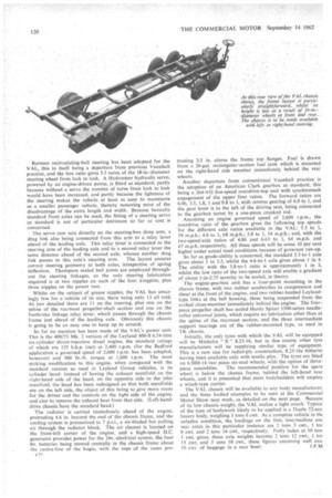
The VAL chassis will be available to any body manufacturer, and the three bodied examples to be seen at the Commercial Motor Show next week, as detailed on the next page. Because of its low chassis weight, the VAL makes a light coach. Typical of the type of bodywork likely to be applied is a Duple 52-sea, luxury body, weighing 3 tons 6 cwt. As a complete vehicle in the unladen condition, the loadings on the first, intermediate anc rear axles in this particular instance are 2 tons 3 cwt., I tor 9 cwt. and 2 tons 14 cwt., respectively. Fully laden at 10 tom 5 cwt. gross, these axle weights become 2 tons 12 cwt., I tor 15 cwt. and 5 tons 18 cwt., these figures assuming well ove 10 cwt of baggage in a rear boot. J.F.M