 1
1 2
2 3
3 4
4 5
5 6
6 7
7 8
8 9
9 10
10 11
11 12
12 13
13 14
14 15
15 16
16 17
17 18
18 19
19 20
20 21
21 22
22 23
23 24
24 25
25 26
26 27
27 28
28 29
29 30
30 31
31 32
32 33
33 34
34 35
35 36
36 37
37 38
38 39
39 40
40 41
41 42
42 43
43 44
44 45
45 46
46 47
47 48
48 49
49 50
50 51
51 52
52 53
53 54
54 55
55 56
56 57
57 58
58 59
59 60
60 61
61 62
62 63
63 64
64 65
65 66
66 67
67 68
68 69
69 70
70 71
71 72
72 73
73 74
74 75
75 76
76 77
77 78
78 79
79 80
80 81
81 82
82 83
83 84
84 85
85 86
86 87
87 88
88 89
89 90
90 91
91 92
92 93
93 94
94 95
95 96
96 97
97 98
98 99
99 100
100 101
101 102
102 103
103 104
104 105
105 106
106 107
107 108
108 109
109 110
110 111
111 112
112 113
113 114
114 115
115 116
116 117
117 118
118 119
119 120
120 121
121 122
122 123
123 124
124 125
125 126
126 127
127 128
128 129
129 130
130 131
131 132
132 133
133 134
134 135
135 136
136 137
137 138
138 139
139 140
140 141
141 142
142 143
143 144
144 145
145 146
146 147
147 148
148 149
149 150
150 151
151 152
152 153
153 154
154 155
155 156
156 157
157 158
158 159
159 160
160 161
161 162
162 163
163 164
164 165
165 166
166 167
167 168
168 169
169 170
170 171
171 172
172 173
173 174
174 175
175 176
176 177
177 178
178 179
179 180
180 181
181 182
182 183
183 184
184 185
185 186
186 187
187 188
188 189
189 190
190 191
191 192
192 193
193 194
194 195
195 196
196 197
197 198
198 199
199 200
200 201
201 202
202 203
203 204
204 205
205 206
206 207
207 208
208 209
209 210
210 211
211 212
212 213
213 214
214 215
215 216
216 217
217 218
218 219
219 220
220 221
221 222
222 223
223 224
224 225
225 226
226 227
227 228
228 229
229 230
230 231
231 232
232 233
233 234
234 235
235 236
236 237
237 238
238 239
239 240
240 Twin In-line from Brockhouse
Page 118
If you've noticed an error in this article please click here to report it so we can fix it.
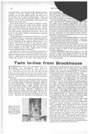
INDEPENDENT trailers and semi-trailers with twinoscillating axle arrangements were made by J. Brockhouse and Co., Ltd., for many years up to 1939. Since the end of the war only one unit with this layout has been produced, but now the company have re-entered this particular market with a new 15-ton model— • the 4-15. An example is to be exhibited at the Commercial Motor Show.
Each axle is carried on a trailing link pivoted at the front end on widely spaced bearings mounted on the underside of a full-width hollow box-section cross-beam, welded to the frame side-members. The only suspension media are Aeon pillow-type hollow rubber springs, one being mounted on the frame above each trailing link and on the centre line of the axles. Rebound is restricted by steel cables behind the springs and there is provision for the fitting of dampers at the ends of the links. The axles are at 4-ft. 3-in, centres and the pairs of wheels at 2-ft. 4-in. centres. The axles are mounted on the underside of the trailing links in bearings which allow for lateral oseillatioi Stops restrict this to 100 on either side of the verticai Girling 15.25 in. by 4.25 in. two-leading-shoe brakes ar employed (the standard braking system is air-pressure assisted hydraulic) and the tyres are 10.00-20, 16-ply.
Pressed-steel frame side-members by John Thompsoi Motor Pressings, Ltd., or Rubery Owen, Ltd., and pressed steel cross-.members and outriggers give a clean appearanc to the semi-trailer. The side-members are 15 in. dee] reducing to 7.375 in. from behind the coupling plate an
in. thick. Above the box-member carrying the trailing link pivots, and above the rubber spring location, larg. gusset plates are welded to the inside of the frame and th• members. Support for the fifth-wheel coupling plate i given by two frame cross-members and a full-width fron cross-member. The landing gear employed on the semi trailer is the new Model VG450 wind-down leg gear fron Davies Magnet Works, Ltd. These are available in single or two-speed form and are produced in a fabricated desigi using square-section, steel casings and support tubes.
Fabricated corner posts support the front timber head board, which also carries the braking system units. Thes are mounted as a unit on the front of the headboard am comprise a Clayton Dewandre air-pressure servo am valves, a hydraulic master cylinder and the fluid eontaine2
Standard length of the semi-trailer is 25 ft., but an: length up to 28 ft. (the maximum length obtainable of th• side-member pressings) and 7 ft. 6 in. or 8 ft. widths can b obtained. The side rails are of 6.5-in.-deep rolled-stec section, and these are welded to the frame outriggers t■ suit the operator's requirements—to give a flush floor or ; raised edge, and so on. The platform height depends oi the thickness of flooring timber, but will be about 4 ft. 6 in at the front and 4 ft. 3 in. at the rear of the platform.
Other items of standard equipment are flashing directioi indicators, stop and tail lights and reflectors.