


How to Keep Your Lorry Fit. --V.
Page 5
Page 6
Page 7
If you've noticed an error in this article please click here to report it so we can fix it.
This Article Deals with the Austin 2-3-ton Chassis.
Austin chassis are of distinctive design. This characteristic is common to all Austin productions ; so much so, that shortly, no doubt, we shall arrive at a period when mention of Austin vehicles will be possible without drawing attention to it. The line of heavy vehicles is confined to two sizes, one described as a 2-3-ton chassis, and the other is a 15-tonner. We dealt with both of these vehicles very fully in our pages on dates 13th February, 1913, and 24th February, 1916, respectively. We do not need, therefore, on this occasion to devote any further space to descriptive matter. Owing to the war and its effect on production, only the 24,-ton Austin has been sold in any quantities to commercial users. We will in consequence devote our attention to this model. It is a fact, nevertheless, that the design of these chassis is so very similar that the one article would almost suffice to cover the details of both.
Care of the Austin chassis is a simple matter, and the instructions needful are given in non-technical language and concisely in the coin
., pany's handbook. These instructions are supplemented, as occasion demands, by timely hints and tips in the House Organ of the Austin Motor Co. (1914), Ltd., which is styled " The Advocate," and which is published monthly. ' As both handbook and periodical will be supplied gratis and with pleasure to any bona fide user of Austin vehicles, we recommend every owner to write to Longbridge Works, at Northfield. Birmingham. asking for a copy of the former and that he may be put on the mailing list for the latter.
The following instructions are based upon information supplied in these books and, in some cases, textual matter is reproduced as it stands ; furthermore, all the illustrations are obtained from one or other of these sources. As is customary, we commence with a few notes on lubrication.
A matter which does not usually receive the amount of consideration it undoubtedly deserves is that of selecting the right brand -of oil. The Austin Co. recommend Price's Gas Engine Oil, or one of equal viscosity. The importance of the careful selection is due to the fact that if thick oil were used on a cold day the pump might be strained and the gauge broken. Oil which is too thin might not have sufficient body to ensure a film of lubricant between the bearings and journals, and would, therefore, not perform its function. The oiling of the Austin engineis accomplished by the aid of a double pump. One of these sucks oil from the oil tank situated under the bonnet, and forces it to the various bearings ; the other one draws from the oil which collects inthe bottom of the base chamber and carries it back to replenish the tank. This tank should be filled to within 2 ins, from the top, and a daily inspection made to ensure that the revel is maintained. A fresh supply of oil should be provided every 1000 miles. Once every three months the gauze filter in the oil tank should be washed with paraffin, care being taken to replake it properly. If the pressure in the oil system is too high, there is a tendency for. the engine to smoke. TO reduce pressure, unscrew the oil relief valve which appears on the top of the crankcase at the front end of the engine. A pressure gauge on the dash serves at once to indicate if the oil -supply has failed. In the event of such failure, one of the following will be the cause : either (1) there is not. sufficient oil in the tank, (2) the pump or oil pipes have broken, or may be the pressure gauge has failed, (3) the suction pipes may be choked, (4) the pump vanes may be sticking owing to the use of dirty oil.
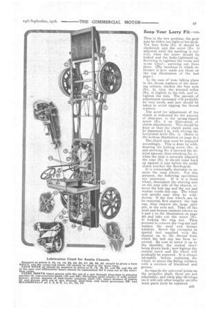
The oil in the gearbox should be replenished weekly. In -order to do this, open the level cock and unscrew the filler cap (No. 16 on the oiling chart), pour oil into the filler cap until the level or overflow cock commences to drip. The oil should be drained from the box, the box
cleaned with paraffin, and new oil supplied once every three months. The remainder of the oiling instructions will be found beneath the oiling chart which accompanies this article.
The water pump on the Austin engine requires occasional inspection. The gland for preventing the escape of water along the spindle should be tightened up from time to time. If such tightening fails to stop any leakage, fresh packing is necessary. As a preliminary to supplying this, slack back the locking nut and remove the gland nut. The brass sleeve which comes into view when the nut is remOved should be pulled out as far as possible. The packing can then be removed and fresh asbestos string, soaked in lubricating oil or hot tallow fat, can be wound on the spindle and forced into position in sufficient quantity. The gland Must not be packed too full, and it should he possible to insert the sleeve one-sixteenth of an inch before it touches the. packing; it will be sufficiently tight, when, if the nut be screwed down, half the sleeve will have entered the gland. It is sometimes necessary for the purpose of cleaning, or on some other occasion, to remove the cylinders. In that event, the following is the method of procedure recommended. Drain out all water by the tap provided on the pipe leading from the radiator to the water pump ; disconnect the water pipe on top and the rubber connections between cylinders ; uncouple the petrol, induction, and exhaust pipes ; unscrew the four nuts holdingtthe cylinder to the crankcase, and carefully raise it. Be careful that the open end of the ,piston is not allowed to swing on to the connecting rod, as it is likely to fracture, the metal of this point being very thin. As soon as the cylinder is removed, place a sheet of brown paper or other suitable materiaj over the hole in the crankcase, so that no dirt or foreign obje,ct will be allowed to drop into the crank chamber.
When replacing the cylinder, the utmost care must be taken to see that every part is perfectly clean. B26 Before lowering it on to the piston, examine the rings to see that the opening of each is in line with the little peg which keeps the ring from turning ; put plenty of oil on the piston. Take care not to damage the rubber ring making the water joint between the cylinders. The holding-down bolts (four in number) should be tightened up firmly and equally. Da not tighten them to the fullest extent in turn, but as the nuts begin to bed on the casting, screw each of them up a little, so that the final tightening of each is a very small amount. To remove a piston or connecting rod, or to take up the big ends of the crankshaft bearings, take off the bottom half of the crankcase and the side doors, when it will be a simple matter to uncouple the bolts in the connecting rod ends should it prove necessary. Pistons cannot be taken out without first removing the cylinders.
It is important to give an occasional eye to the wear on the makeand-break of the magneto. If the points become too far. apart for any reason, a weak spark will be given at low speeds. Maladjustment here affects the timing of the spark be
cause thebreak will occur at some point when the current generated is not at its maximum. This is most noticeable at low speeds and will affect the easy starting of the engine. To correct it, the adjustable platinum-tipped screw should be so regulated that the gauge or feeler on the magneto spanner can just be inserted between the platinum. points. If the points are out of order owing to burning or wear, they should be very carefully filed flat with the finest available file.
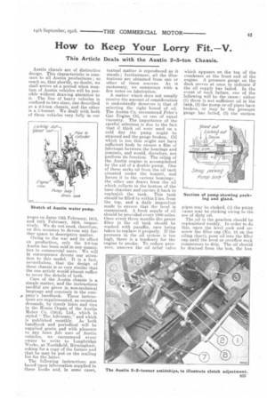
A few hints about the steering gear are well worth repeating. Never attempt to alter the steering lock while the lorry is stationary. The steering gear on the Austin comprises a complete worm wheel and worm instead of the more customary sector and worm. This allows of three new working positions for use when wear has taken place in the wheel. In such an event, when the teeth of the wheel have become too much worn to be of any further use as originally set, the steering lever should be taken off the square end of the shaft, and the hand wheel turned until one quarter revolution has been given to the worm wheel ; the lever may then be put back on the shaft and secured. A screw (No. 1) is provided for adjusting the depth of meshing of the worm and wheeL Thus in the new position, the gear may be either too tight or too slack. The four bolts • (No. 2) should be slackened, and the screw (No. 1) adjusted until the meshing is correct, when the screw should be locked and the bolts tightened up. Screwing in tightens the worm and worm wheel ; screwing out frees them. (The numbers to which reference is here made are those on the top illustration of the last page.) In the ease of wear taking place in the thrust washers of the steering column, slacken the four nuts (No. 3), turn the knurled collar (No. 4) slightly to the left, and retighten the nuts. The amount, of adjustment necessary will probably be very small, and .care should be taken to avoid nipping the thrust washers.
The need for adjustment of the
clutch is indicated by the amount of clearance in the spring-tipped screw (No. 2 on illustration of clutch adjuStinent). This should be kept so that the clutch pedal can be depressed 4 in. with moving the horizontallever (No. 1). (Refer.: to the bottom illustration on page 45.)
The clutch stop must be adjusted accordingly. This is done by withdrawing the locking screw (No. 4) and screwing No. 5 forward the desired amount, then relocking No. 4; when the stop is correctly adjusted the cone (No. 6) should coine hard up against it just before the pedal clutch touches the floorboards.
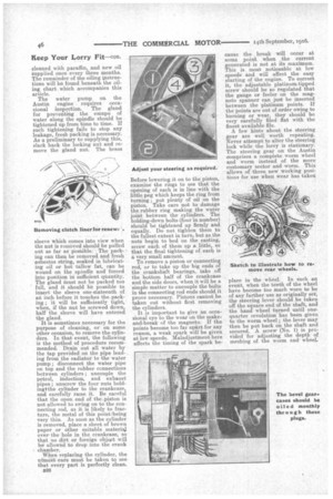
It is occasionally desirable to remove the road wheels. For this purpose, the following operations
are necessary. If it is a front wheel, disconnect the steering arm on the near side of the chassis, remove the hub cap and the nut and washer inside this cap. The wheel and spindle may then. be withdrawn. If the rear wheels are to be removed, first unscrew the hub cap, then remove the large split pin, . in the axle nut. Take off the steel and bronze washers (shown as -3 and 4 on the illustration on page 46) and take out the screw (No. 5) locking the ring nut. Then proceed to remove the ring nut and replace the steel and bronze washers. Screw the extractor ,(a Special tool supplied with the chassis) on to the thread from which the hub cap has been removed. Be sure to screw it up to the shoulder, the central screw being drawn back ; now tighten the central screw and the wheel will gradually be removed. It is always advisable, before replacing the wheel, to smear the fitting surface's with a mixture of blacklead and grease.
As regards the universal joints on the propeller shaft, these are pot adjustable, and when play develops (as it will only after lengthy use)the worn parts must be replaced.