


Two-fuel Carburetters and Fittings.—XVII.
Page 4
If you've noticed an error in this article please click here to report it so we can fix it.
Another American Device Described by Mr. Sturmey.
A new paraffin fuel system, which is meeting with considerable success in America at the present time and appears to be a practical solution of this none-too-easy prob
may be of. interest to readers of TIIE CO3i.VERCIAL MOTOR. Unlike most of the devices which have recently Made their appearance, it is not merely-a modification of a heated carburetter, but.a complete system, replacing not only the carburetter, but both the exhaust and inlet manifolds.
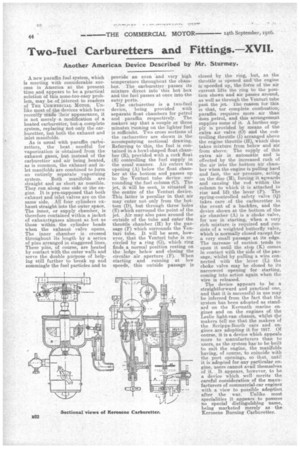
As is usual with paraffin carburetters, the heat needful for vaporization is obtained from the exhaust gases, but instead of the carburetter and air being heated, as is common, the exhaust and inlet manifolds are combined to form an entirely separate vaporizing system. Both manifolds are straight and as short as possible. They run along one side of the engine. It is pre-supposed that both exhaust and inlet valves are on the same side. All four cylinders exhaust straight into the outer space. The inner, or supply chamber, is therefore contained within a jacket of exhanstagases almost as hot as those within the cylinder beads when the exhaust valve opens. The inner chamber is crossed throughout its length by a series of pins arranged in staggered lines. These pins, of course, are heated by contact With the outer walls and serve the double purpose of helping still further to break up and commingle the fuel particles and to provide an even and very high temperature throughout the chamber. The carburetter passes its mixture direct into this hot box and the fuel passes at once into the entry ports. The carburetter is a two-fuel device, being provided with separate float chambers for petrol and paraffin respectively. The makers say that a couple or three minutes running on the lighter fuel is sufficieht. Two cross sections of the carburetter are shown in the accompanying sectional drawing. Referring to this, the fuel is contained in a bowl-shaped float chamber (R), provided with a cork float (S) controlling the fuel supply in the usual manner. Air enters the opening (A) below the float chamber at the bottom and passes up to the Venturi tube device surrounding the fuel column (Q. The jet, it will be seen, is situated in the centre of the Venturi device. This latter is peculiar in that air may enter not only from the bottom (D), but through three holes (E) which surround the point of the jet. .Air may also pass around the outside of the tube and enter the throttle chamber (H) by the passage (F) which surrounds the Venturi tube. It will be seen, however, that the Venturi tube is encircled by a ring (G), which ring finds a normal position resting on the ledge below and closing the circular air aperture (F). When starting and running at low speeds, this outside passage is closed by the ring, but, as the throttle is opened and the engine is speeded up, the force of the air current lifts the ring to the position shown and air passes around, as well as through the Venturi tube past the jet. The reason for this is that, tor complete combustion, paraffin requires more air than does petrol, and this arrangement supplies some of it. A further supply is provided by means of the extra air valve (0) and the controlling throttle (I) arranged above the engine throttle (H), which' thus takes mixture from below and air from above. The supply of this extra air is automatic and is effected by the increasedrush of the air into the bottom air chamber when the engine is pulling hard and fast, the air pressure, acting on the disc (31), forcing it upwards and causing the rod within the column to which it is attached to rise and lift the lever (P). The spring-controlled safety valve (Q) takes care of the carburetter in the event of a backfire, and the device shown at the bottom of the air chamber (A) is a choke valve, for use in starting, when a very rich mixture is required and consists of a weighted butterfly valve, which is normally closed except for a very small passage at its edge. The increase of suction tends to open it until the stop (K) comes in contact with the side of the passage, whilst by pulling a wire connected with the lever (L) the choke valve may be closed to its narrowest opening for starting, coming into action again when the wire is released.
The device appears to be a straightforward and practical one, and that it is successful in use may be inferred from the fact that the system has been adopted as standard on the Kermath marine engines and on the engines of the Leslie light-van chassis, whilst the makers tell me that the makers of the Scripps-Booth cars and engines are adopting it for 1917. Of course, it is a device which appeals more to manufacturers than to users, as the system haste be built to suit the engine, the manifolds having, of course, to coincide with the port openings, so that, until it is adopted for any particular eni gine, users cannot avail themselves of it. It appears, however, to be a device which well merits the careful consideration of the manufacturers of commercial-car engines with a view to possible adoption after the war. Unlike most specialities it appears to possess no special distinguishing name, being marketed merely as the Kerosene Burning Carburetter.