Patents Completed.
Page 22

If you've noticed an error in this article please click here to report it so we can fix it.
Pressure-feed Tanks. Multi-tubular Varying Fuel Feed. Variable
Cantilever Springs. A New Sparking Plug.
Copies of complete specifications of the patents published on this page can be obtained from the Sales Branch, Patent Office, Holborn, W.C., at the cost of sixpence for each specificatiorz.
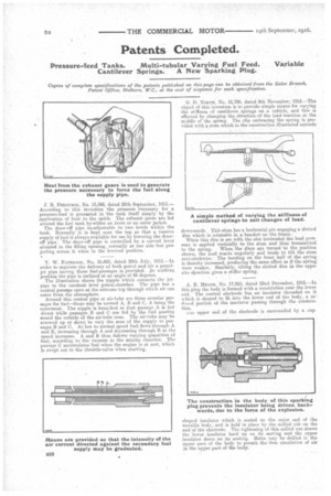
J. B. FialGusow, No. 13,368, dated 20th September, 1915.— According to this invention the pressure necessary for a pressure-feed is genesated in the tank itself simply by the application of heat to the spirit. The exhaust gases are led around the fuel tank bpeither an inner or an outer jacket. The draw-off pipe is adjustable to two levels within the tank. Normally it is kept near the top so that a reserve supply of fuel is always available for use by lowering the drawoff pipe. The draw-off pipe is controlled by a curved lever situated in the filling opening, normally at one side but projecting across it when in the lowered position.
T. W. PATERSON, No. 10,493, dated 20th July, 1915.—In order to regulate the delivery of both petrol and air a petrol. jet pipe having three fuel-passages .is provided. Jri working position the pipe is inclined at an angle of 45 degrees.
The illustration shows the nipple which connects the jet. pipe to the ()constant level petrol-chamber. The pipe has a central passage open at the extreme top through which air can enter from the atmosphere. Around this central pipe or air-tube are three annular passages for fuel—these may be termed A, B and C, A being the outermost. The nipple is branched so that passage A is fed direct while passages B and C are fed by the fuel passing round the outside of the air-tube nose. The air-tube may be screwed up or down to vary the area of the supply to passages B and C. At low to normal speed fuel flows through A and B, increasing through A and decreasing through B as the speed increases. A and B thus deliver varying quantities of fuel, according to the vacuum in the mixing chamber. The passage C accumulates fuel when the engine is at rest, which is swept out to the throttle-valve when starting. •
0. D. NORTH, No. 15,736, dated 8th November; 1915.—The object of this invention is-to provide simple means for varying the stiffness of cantilever springs on a vehicle, and this is effected by changing the direction-ofthe loadreaction at the middle of the spring. The clip embracing the spring is provided with a stern which in the construction illustrated extends
downwards. This stem has a horizontal pin engaging a slotted disc which is rotatable in a bracket on the frame. • When this disc is set with the slot horizontal the load pressure is applied vertically to the stem and thus transmitted to the spring. When the discs are turned to the position shown, the load reacts angularly and tends to tilt the stem anti-clockwise. The bending on the front half of the spring is thereby increased, producing the same effect as if the spring were weaker. Similarly, tilting the slotted disc in the opposite direction gives a stiffer spring.
A. E. HEATH, No. 17,911), dated 22nd December, 1915.—In this plug the body is formed with a constriction near the lower end. The central electrode has an insulator threaded on it which is shaped to fit into the lower end of the body, a re-' shaped insulator which is seated on the outer end of the metallic body, and is held in place by the milled nut on the end of the electrode. The tightening of this milled nut draws the lower insulator hard up on its seating and the upper insulator down on its seating. Holes may he drilkd in the upper part of the body to permit the free circulation of air in the upper part of the body.Tags


