


Albion Patent Mechanical Lubricator.
Page 8
Page 9
If you've noticed an error in this article please click here to report it so we can fix it.
Motor Manufacturers can acquire a License to Fit this Valuable Invention.
Considerable attention has been drawn of late, both by the Press and by the Automobile Club of Great Britain and Ireland, to the objectionable practice at present prevailing of over-lubricating care, causing thereby a smeky, evil-smelling exhaust, which is due in the majority of cases to the fact that fear of under-lubrication causes the majority of drivers to over-lubricate their engines. Over-lubrication leads in most cases to intermittent ignition due to the sooting up of the plugs, the choking of the silencer with resultant loss of power due to back pressure, and the gumming up of the valves ; also, when there is too much lubricating oil present in the cylinders, a portion of this oil gets carried through the silencer, and burns there, causing the offensive smell associated with the exhaust of so many cars. The Albion patent mechanical lubricator, full details of which became available on Monday last, has been designed to overcome these
objectionable features, and to ensure efficient, certain, and uniform lubrication at all times. It has been in use for many months, and has undergone a thorough series of road tests, including the Scottish A.C. reliability trials, when a solid-tyred Albion, fitted with this lubricator, was awarded the gold medal in its class. One i.nportant advantage is that it requires no attention on the part of the driver. All that is necessary is for him to see that there is eil in the lubricator, and to set its rate of feed in accordance with instructions issued with the car. After this has been done the lubricator will deliver under pressure, by means of A
valveless pump, a definite quantity of oil to each oil-pipe. The rate of feed is proportional to the speed of the motor, so that the faster the engine is running the more oil is delivered to it, and vice versa.
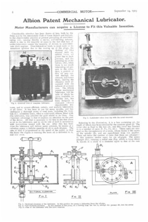
Fig, A.—External view of complete lubricator.
Referring to the illustration, A is a box containing oil, the depth of which may be ascertained by the contents glass (J). The cover (As) is fixed to the box (A), and this cover has inserted in it a number of cams (F, Ft, F2, etc.). These cams are situated on the circumference of a circle, whose eentre is the centre of the spindle (13t, and are equi-distant from one another. There are twice the number of cams that there are oil-pipesin this instance twelve cams for six oil-pipes. The pump plunger (Es), carrying a radial arm (1:4), which is loose about 13, travels in a circle of a diameter equal to that of the cam
circle. This pump plunger (Ex) has at its upper extremity a roller (E3), and this roller is held up against the cams (F, Fa, Fa, etc.) by the spiral spring (E2). The pump cylinder (E) is in one piece with the disc (C), and rotates with it. The disc (c; is fixed by a sliding feather to the central spindle (B), and oil-tight surface contact is maintained between C and the stationary disc (Bat by the spiral spring (Ca). The disc (C) is
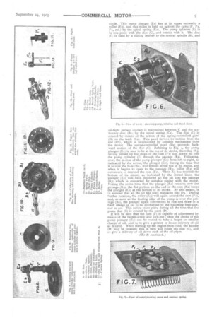
actated by means of the action of the spring-controlled pawl (D) an the teeth (Ca). This pawl derives its motion from the rod (Da), which is aeciprocated by suitable mechanism from the motor. The spring-controlled pawl (1)2; prevents backward motion of the disc (C). Referring to Fig. 2, the pump plunger (Et) is seen to be at the top of its stroke, the roller (E3) having passed up the slope of the cam (Fa) and drawn oil into the pump cylinder (E; through the passage (B2). Following, now, the motion of the pump plunger (Ex) from left to right, as indicated by the arrow, the plunger (Ea), during the time that it is over the hole (132;, will remain at the top of its stroke, and when it begins to open to the passage (B3), roller (E3) will commence to descend the cam (Fa). When E3 has reached the bottom of its stroke, as indicated by the dotted lines, the plunger (Ea) will have displaced all the oil into the passage (83) which is connected by suitable piping with the motor. During the entire time that the plunger (Ex) remains over the passage (83), the flat portion on the end of the cam (Fa) keeps the plunger (Ex) at the bottom of its stroke. By this means, it in ensured that all the oil has been displaced into D3. During further rotation, the roller (E3) will again ascend the cam (Fa), and, as soon as the leading edge of the pump is over the passage (82), the plunger again commences to rise and draw in a fresh charge of oil to be discharged to the following feed-pipe, and so on. This action takes place during all the time that the pump disc (C) is rotated by the pawl (I)).
It will be seen that the cam (F) is capable of adjustment by means of the thumb-screw and lock-nut ; thus the stroke of the pump plunger (Et) can be varied to take a larger or smaller charge of oil, and so to give a greater or lesser delivery of oil as desired. When starting up the engine from cold, the handle (H) may be rotated; this in turn will rotate the disc (C), and so give a delivery of oil down each of the oil-pipes.
(To be continued.)