


TRIAL OR CALCULATION )ETERMINE GRADEABILITY ?
Page 26
Page 27
Page 28
If you've noticed an error in this article please click here to report it so we can fix it.
rnl-IE hill-climbing ability of a vehicle can be discovered I by the following four methods:—
(1) By actual gradient tests, applying various loads to vehicles and observing the speeds they can maintain on a series of known gradients.
(2) By theoretical calculation from engine torque and power curves.
(3) By acceleration and deceleration tests in which the drawbar effort available at various road speeds over the .entire useful speed range of each gear is determined.
(4) By drawbar dynamometer tests which measure the .drawbar pulr available over the entin:.. useful speed range of
each gear. • Influenced by a possibility of the introduction of a minimum speed limit on hills of certain steepness,, to prevent traffic delays by heavy vehicles, the American Bureau of Public Roads has recently undertaken a complete range of investigations on new commercial vehicles to find the relative merits of the different methods.* In the Bureau's report the engine characteristics and other particulars of the chassis investigated are not given.
As it is said that the lorry was in first-rate condition, one will understand that the results are not valid for vehicles of crinsideratile age and diminished efficiency, also the quality of driving will have some influence on performance. Therefore, the results obtained can be regarded as optimum values, which may be multiplied by an efficiency factor, leas than one, to obtain conditions comparable with vehicles in actual service, The three large graphs on these pages show in full lines the gradeability in third gear of a lorry, with various loads and on five different gradients, arrived at by calculation from engine torque, by calculation from acceleration tests and by trials with a dynamometer vehicle towed behind the lorry, respectively.
On the graphs are also. indicated the gra,deability revealed by actual trials on the various gradients.
Actual gradient tests are, in any case, the most promising and effective method, but are laborious and expensive and afford no short cut to a result. In these ,tests, known loads have been applied to the vehicle, and the maximum speed which can be maintained on known slopes has been determined separately for each load. The maximum gross weight that could be propelled up the hill at a constant speed in a given gear was determined by trial, then the load was lessened in decrements of 1,00 lb.
This operation was continued until the road speed represented approximately the maximum r.p.m. recommended by the manufacturer. The tests were repeated in the next higher gear ratio.
Several test runs on the hill were necessary in determining the maximum maintained speed for each load. The truck approached the grade from the level at a speed intended to be maintained over the entire trial section, all tests tieing made with full throttle, Besides a speedometer, to serve as a guide, the machine was equipped with a special time-distance recorder giving distances at 10-second intervals, from which the average speed could be calculated with an error of less than 1 per cent.
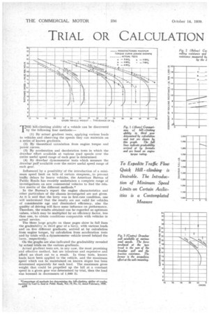
Fig. 1 contains dotted curves plotted from the results of tests using third gear. This supplies basic data with which the results obtained from the other methods are compared. With regard to theoretical performance, shown in Fig. 1 in full lines, the gross vehicle weight, W, in pounds, which can be carried up a gradient, G (in feet of rise per foot), at a given constant speed, can be calculated by means of the following formula:— .
T = torque at a given engine speed, in lb.-ins. (usually taken from engine performance curves).
E = overall efficiency of vehicle. •
R = total gear reduction.
r = rolling radius of tyres, in inches.
I = co-efficient. of rolling resistance, in lb. per lb. of weight.
The curves of the calculated hill-climbing ability are plotted on the assumption that E = 0,85 and f = 15/1,000. The results of the two methods correspond remarkably closely, except over the peak-torque range. The curves, however, would coincide also in these cases if, instead of f equalling 15/1,000, a value of 10/1,000 had been assumed, equivalent to 0-.5 per cent, of gradient. Deceleration tests at road speeds at which the peak torque was developed showed this value to be the more accurate.
Acceleration and deceleration tests were carried out on a level section of road, The lorry was accelerated in each gear at full throttle, starting at the lowest speed at which the engine would operate smoothly and continuing to the maximum recommended engine speed. Deceleration tests were made on the level by first attaining the desired speed and then permitting the vehicle to coast in neutral. For acceleration the following relation exists:— Drawbar pull, P = a (M + KO lb. For deceleration the relation is:—
. Tractive resistance, R= —a' (M + K0) lb. where
a — acceleration of vehicle, in ft. per sec. per sec. —a' = deceleration, in ft. per sec. per sec.
M = w + g = mass of vehicle. w = net weight of vehicle.
g = acceleration due to gravity, 32.2 ft. per sec. per • sec.
Ku mass-equivalent constant for the vehicle operating in a given gear.
I-co= mass-equivalent -constant for vehicle coasting. The factors K and Ku are due to the rotating parts of the vehicle, storing up energy when the vehicle is accelerating. Drawbar pull is the force produced by the driving wheels as thrust on the bearing housings.
To convert drawbar pull P to hill-climbing ability the following relation holds good:—
F = W.G + W.f w.f
P — f (W w) from this G The single values are already given. w.f = tractive resistance of accelerating vehicle at a speed for which the drawbar pull was measured. W.G = grade resistance.
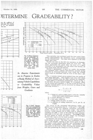
w.f = tractive resistance of vehicle on grade. For determining the hill-climbing ability, from these erprations, it is necessary to know, besides the weight of the vehicle and its load, the drawbar pull F and the rolling
resistance f = R W in their relation to speed. In Figs. 2 and 3 these values are given and from them can be calculated the relation between speed and gross vehicle weight which are compared in Fig. 4 with the grade tests. In drawbar dynamometer tests a special dynamometer developed by the Ordnance Department of the United States Army was used, consisting of a 10-ton vehicle equipped with two fire pumps. These are connected to the main propeller shaft by a two-speed auxiliary gearbox. When the dynamometer vehicle is towed by the test vehicle the rear wheels of the trailing unit actuate the pumps, forcing water from a tank through a pipe with an adjustable orifice and then back to the tank.
By regulating the size of orifice the discharge pressure of the pump can be increasedor decreased, which, in turn, increases or decreases the torque required to turn the rear
wheels. Drawbars, each composed of a cylinder and piston, are mounted on the front and rear of the dynamo
meter truck. When the test vehicle tows the artificially loaded dynamometer truck, the pressure in the cylinder is recorded, allowing the available drawbar pull to be-determined. Resistance to traction is ascertained by towing the test vehicle behind the dynamometer.
Fig. 2 shows also the results obtained by this method;. there is again a tendency for the rolling resistance to increase with the speed; the absolute values, however, are considerably higher. The original report showed curves of wavy form, but these are not justified.
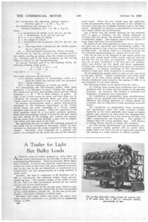
By means of the same equations as used above, the drawbar pull can he converted into hill-climbing ability; the results are given in Fig. 5 and are compared with the-actual gradient tests. As before, there is a variation between the two methods approximating to a grade of 0.5 per cent.
This can be seen in the diagram as the square points for 4.5 per cent. actual grade ability nearly coincide with the full line for 4,0 per cent. as computed. The discrepancy may be, in part, attributed to the fact that the dynamometer was evolved for low speed and heavy equipment, therefore the values for lower gears and speed are in better conformity. A distinct advantage of the dynamometer method is that only little calculation is necessary.
All aecompanying graphs relate to tests of only one truck in one gear (third). Similar comparisons have been made for each of 18 units tested during the autumn of 1938. Besides additional unit§ tested in the spring of 1939, 'it is also intended to test used vehicles.
The following results can be drawn from the tests:— (I) Testing under actual load conditions over several gradients will, of course, provide results of the greatest accuracy: As, however, this method is laborious and expensive, its general use is precluded.
,(2) Calculation of gradeability from manufacturers' torque curves, provided that reliable factors for overall efficiency and rolling .resistance at various speedsare available, may be expected to yield reasonably accurate results.
(3) Calculation of gracleability from acceleration and deceleration tests will yield accurate results, especially in the more generally used range of engine speeds, and requires no data from the manufacturer. Complete tests require but a few hours in the field, but;
office computations are, laborious, The method is cheaper than the actualgradient tests. (The Bureau of Public Roads intends to adopt this method.) (4) The towing dynamometer can undoubtedly produce accurate results quickly and in usable form. High initial cost limits its use to operations .requiring the testing of a large number of vehicles quickly.