


THE BEARDMORE TWO-STROKE ENGINE.
Page 30
If you've noticed an error in this article please click here to report it so we can fix it.
A Résumé of Recently Published Specifications.
OST two-stroke engines are so con structed that the exhaust ports, which are cut in the walls of the cylinders, are uncovered by the piston as it nears the end of its working stroke. Specification No. 221,010 refers to twostroke engines of that type, and particularly to those which are provided will, auxiliary and main exhaust ports, of which the former are uncovered first. There is a separate passage which leads from the auxiliary exhaust ports of each cylinder to an ejector nozzle so disposed in the passage leading from the main exhaust port of one of the other cylinders as to exert an ejector effect and thus facilitate and expedite the flow of the products of combustion from that cylinder and the entry of the charge into the cylinder.
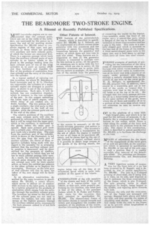
In a typical method of carrying out this invention, for which W. Beardmore, Lord lnvernain and A. E. L. Chorlton are responsible, the cylinders of a mniticylinder engine are arranged in parallel pairs, as shown in one of the accompanying illustrations. Each pair, it will be noticed, has one combustion chamber, which is common to the two cylinders of the pair. In this respect resembling the Lucas type of petrol engine, with which many of our readers are, no doubt, familiar. The two pistons act on a single crankpin; the inlet ports to that pair are situated in the wall of one cylinder, while the exhaust ports are cut in the wall of the other.
The relative positions of the auxiliary and main exhaust ports will also he gathered by reference to the illustration, and it will be noted that the upper port, which is the auxiliary, is uncovered by the piston before the -main port is opened.. Each main exhaust port leads into a suitable pipe, Whilst each auxiliary port leads into a smaller pipe. The pipe from the auxiliary port of the cylinder, which is shown in the illustration, is led into the pipe from the main port of another cylinder, the choice of these respective cylinders being made with due regard to the necessity for so arranging matters that the auxiliary exhaust port in question is uncovered, and its gases utilized for the purposes of ejection, when the cylinder to which they are led has its main exhaust passage fully open. As a result, the relatively high-pressure exhaust gases escaping from the auxili
ary exhaust port will, by their ejector action, so lower the residual gas pressure in the other cylinder as to improve the scavenging. Moreover, as the inlet port of that cylinder will also be open, the inflow of the new charge will be facilitated.
• In an alternative construction, described by the same inventors in specifi
cation No. 221,011, a rotary blower, which serves to deliver air or combustible mixture to the inlet ports, is driven by a turbine actuated by the products of combustion which escape from the cylinder through the auxiliary exhaust ports. The inventors lay stress on the fact that all the exhaust gases are not used to actuate the turbine, but only such as escape at the highest pressure through the auxiliary exhaust ports, consequently the back pressure caused is of but little consequence.
046
Other Patents of Interest.
THE features of the petrol-electric
chassis, which is described in specification No. 220,980, by J. Schurch, are the employment of a direct-current series generator with two armatures and the provision of means for controlling the connections between the generator and motors, of which there are two—one to each rear wheel. These features are incorporated so that (1) the Fenerator armature is connected in multiple with the two motors in series; (2) the generator armatures are in series with the two motors, which are also in series; (3) the generator armatures are in series, with the two motors in multiple; (4) the direction of the current from the generator
to the motors is reversed; or (5) the circuit between generator and motors is disconnected altogether. The inventor's object is to provide a transmission by the aid of which the engine is enabled to run at all times at its maximum efficiency, and he claims that by the use of the methods of control outlined above it is possible to obtain large torques at low speeds of the driving wheels, the engine being run all the time at an economical speed which is quite independent of the speed of the wheels.
COMBINATION of the side members of the chassis and body of the trailer portion of a tractor-trailer type of vehicle, so that each, while properly performing its own function, also takes part in that of the other, is the principal feature which E. R. Foden and Fodens, Ltd., claim for the invention they have patented in specification No. 2'21,035. The channel-steel frame of the trailer chassis is turned inwards and covers and strengthens the wooden side members of the platform of the trailer. Another interesting feature is the method of connecting the trailer to the tractor: Cross members under the front of the trailer carry a saucer-like part, which is flanged at the tap to facilitate its attachment to those cross-members and has a gap in the base. This seats in a similarly shaped part which is mounted on the rear end of the frame of the tractor. A third saucer-shaped piece rests in the upper one, and is held there Ly springs which force all three into Clote contact.
FORMER examples of methods of pro viding for the lubrication of the valve stems of internal-combustion eng.ties of the type with which tee are fairobar have embodied a drilled valve in communication at its lower end with a source of oil supply under pressure and leading, through a radially directed hole, to the surface of the bore of the valve guide. W. M. Milligan; in specification No. 221,132, proposes that, in addition, there should be a transverse port cut in the wall of the guide, so located that it registers -with that in the valve, when the latter is at the top of its lift. He arranges that this extra passage delivers the oil to a downwardly directed groove in the outer surface of the guide, down which the oil flows and trickles off on to a portion of the valve stem which would not otherwise be sure to receive any lubricant.
ON to the platform of a lorry with
high hinged sides, and which is to be used for the delivery of minerals, C. A. Roberts fits a comparatively high false bottom in the centre, which forms a ridge along tha middle of the lorry and slopes down to the platform level at the sides. The object of this construction, -which is described in patent specification No. 221,014, is to facilitate the discharge of the load.
MEANS of adjustment for the depth
of the engagement of the bevel gears of an axle are provided, in the construction which is patented in specification No. 213,566, at one end of the axle case, in such a position that it is readily accessible after removal of the detachable wheel. The patentees are SiemensSchuckertwerke Ges. mit I3eschrankter Haftung.
A VERY ingenious system of suspen
sion for the front axle of a car has been, invented by E. Bugatti, and is described by him in patent specification No. 205,488. The axle is a U-shaped pressing of sheet-steel, the U being laid, as it were, on its side, and disposed so that it emigrates the front cross-member of the frame, which is also U-shaped. The axle pressing varies in depth throughout its length, being largest in the middle, and tapering down towards both ends.
Between the axle and the cross-meinirer of the frame are arranged coil springs, disposed bath above and below the axle, and they provide the means of absorbing road shocks. A suitable central clamp holds the axle to the frame, so as to prevent either longitudinal or lateral movement.