


Novel Two-stroke Engine
Page 80
If you've noticed an error in this article please click here to report it so we can fix it.
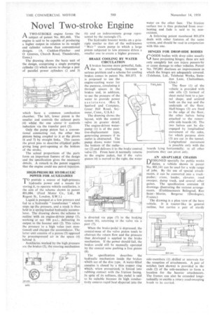
I—% A TWO-STROKE engine forms the
subject of patent No. 801,466. The engine is said to be capable of producing a higher output in relation to its weight and cylinder volume than conventional designs. (A. Cuddon-Fletcher and 0 Greeves, Church Road, Thundersley, Essex.) The drawing shows the basic unit of the design, comprising a single pumping cylinder (1) which serves to charge a pair of parallel power cylinders (2 and 3) which have a common combustion chamber. The left, lower piston is the smaller and controls the exhaust ports (4) whilst the one above it controls induction via the transfer port (5).
Only the pump piston has a conventional connecting rod, the other two pistons being coupled to it at the pivots (6 and 7) by straight links. This causes the pivot pins to describe elliptical paths giving long port-opening at the bottom of the stroke.
The actual proportions of the parts form an important feature of the design and the specification gives the necessary details. A remark in the patent suggests that the engine could use petrol injection.
'HIGH-PRESSURE HYDRAULIC POWER FOR AUXILIARIES
T°provide a source of high-pressurehydraulic power and a means for
storing it, to operate vehicle auxiliaries, is the aim of the scheme shown in patent 801,084. (Ford Motor Co., Ltd., 88 Regent St., London, S.W.1.) Liquid is pumped at a low pressure and fed to a hydraulic " transformer " which steps up the pressure, and a stock is then held in a spring-loaded hydraulic accumulator. The drawing shows the scheme in outline with an engine-driven pump (1), working at say 100 psi., delivering its output to the booster unit (2). This raises the pressure to a high value (not mentioned) and charges the accumulator. The latter unit consists of a piston (3) opposed by precompressed air in the space (4) behind it.
Auxiliaries worked by the high pressure are the brakes (5), the steering mechanism (6) and an indeterminate group represented by the rectangle (7).
The hydraulic booster works on a principle similar to that of the well-known "Weir" steam pump in which a large piston subjected to low pressure drives a smaller one to create a higher pressure.
BRAKE COOLING BY WATER CIRCULATION
A S brakes become more powerful, fade, due to overheating, becomes a serious problem and a scheme for cooling brakes comes in patent No. 801,073. It is proposed to use the engine-cooling water for the purpose, circulating it through spaces in the brakes and, in addition, to use the pressure of the water to provide power assistance. (Roy S. Sanford and Company, Great Hill Road, Seymour, Conn., U.S.A.) The drawing shows the layout, with the control valve in greater detail. The engine-driven waterpump (1) is of the positive-displacement type, generating pressure if its outlet is obstructed. The pump draws water from the bottom of the radia
tor (2) and delivers it to the brake control valve (3). From here it normally returns to the engine jacket, but if the valve piston (4) is moved to the right, the water is diverted via pipe (5) to the braking system (6), returning to the valve via a _port (7). •
When the brake-pedal is depressed, the conical-nose of the valve piston tends to obstruct the return flow and the pressure thus developed is applied to the brake mechanism. If the power should fail, the brakes could still be manually operated by the conical nose pushing a free piston (8) The specification describes the hydraulic mechanism inside the brakes whieh are of the disc type. A Water-filled annulus is closed by 'a 'thin copper ring which.; when pressurized, is forced into rubbing contact with the friction facing. In spite of its softness, this metal is said to be suitable because its 'high conductivity ensures rapid beat dispersal into the
water on the other face. The friction surface too is thus protected from overheating and fade is said to be, non existent. • A following patent numbered 801,074 cleats with other features of the same system, and should be read in conjunction with this one.
HINGES FOR DROP-SIDE BODIES
GOODS bodies with drop sides usually have projecting hinges; these are not only unsightly but can injure passers-by or cause damage to other vehicles. Patent No. 795,881 discloses an improvement in which the hinges are adequately covered. (Telehoist, Ltd., Telehoist Works, Swindon Lane, Cheltenham, Glos.)
The floor (1) of the vehicle is provided with side sills (2) formed of sheet metal bent to a tunnel shape, and secured both on the top and the underside of the floor. Half-hinges (3) are fixed to the edge of the floor, the other halves being attached to the removable side boards (4). The two halves can . be disengaged by longitudinal movement of the sides, for which purpose slots (5) are cut in the tunnel. Longitudinal movement is possible only with the boards lying horizontally; in all other positions they can pivot only.
795,881
AN ADAPTABLE CHASSIS
DESIGNED speciaRy for public works duties, a vehicle shown in patent No. 801,141 can be used for a wide range of jobs. By the use of -special attachments, it can be converted into a truckpusher, crane, loader, elevator, road sweeper, dump truck, and several other guises. The specification contains 18 drawings illustrating the various arrangements. (Etablissements Belingrad, Rue Saint Martin, Bergerac (Dordogne), France.)
The drawing is a plan view of the bare vehicle. It is tractor-like in general outline, but carries a pair of sturdy
side-members (1) .drilled at intervals for the reception of attachments. A pair of notches (not shown) is provided in the ends (2) of the side-members to form a location for the heavier attachments, The frames can also be extended longitudinally to enable a rotary road-sweeping brush to be carried.