


Patents Completed.
Page 22
If you've noticed an error in this article please click here to report it so we can fix it.
DRIVING MECHANISM. — Daimler Motoren Gesellschaft.—No. 25,067, dated ,(under Convention) 8th November, 1905. —This invention relates to driving mechanism for the front steering wheels of a motor vehicle. On the sleeve (n), enclosing the front wheel driving shaft (m), are two, vertically-disposed, collar bearings (f, f) carried by the fork-shaped support (g). Mounted within the bearings f) is a vertical shaft (a) provided with .a turning arm (TO integral with the axle 0) of the wheel (11. Upon. the vertical .shaft (a) located below the axle (b) is Sr.
!ranged a sleeve (k) upon which two bevel gear wheels (p, q) are mounted. The wheel (p) meshes with the bevel wheel (r) mounted on the driving shaft (m), whilst -the second wheel (y) meshes with the wheel (d) arranged on the innex face of the wheel (c). It will be seen that the arrangement of the two gear wheels below the wheel, spindle, or axle, admits of a certain freedom in thc selection of the -transmission ratio, as the driving wheel meshing with the teeth of the front wheel can be arranged higher, or lower, without necessitating any alteration in the construction of the vehicle.
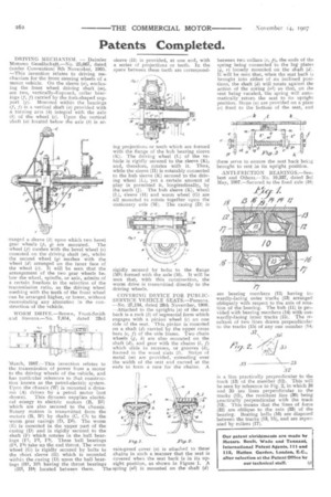
WORM DRIVE.—Brown, Frost-Smith and Stevens.—No. 7 054, dated ' 23rd
March, 1907.—This invention relates to the transmission of power from a motor to the driving wheels of the vehicle, and has particular reference to that construction known as the petrol-electric system. Upon the chassis (W) is mounted a dynamo (A) driven by a petrol motor (not shown). This dynamo supplies electrical energy to electric motors (B, B1) -which are also secured to the chassis. Rotary motion is transmitted from the motors (B, B1) by shafts (C, C1) to the worm gear casings (D, The worm (E) is mounted in the upper part of the casing (D) and is rigidly secured to the shaft (F) which rotates in the ball bearings (El, F2, F3). These ball bearings (E4, F5) take up. the end thrust. The worm wheel (G) is rigidly secured by bolts to the short sleeve (H) which is mounted within the casing (D) upon the ball bearings (H1, 112) having the thrust bearings
)H3, H4) located between them. The
sleeve (II) is provided, at one end, with a series of projections or teeth. In the space between these teeth are correspond ing projections or teeth which arc formed with the flange of the hub bearing sleeve (K). The driving wheel (L) of the vehicle is rigidly secured to the sleeve (K), and, therefore, rotates with it. Thus, while the sleeve (H) is rotatably connected to the hub sleeve (K) secured to the driving wheel (L), yet a certain amount of play is permitted it, longitudinally, by the teeth (J). The hub sleeve (K), wheel (L), sleeve (H) and worm wheel (G) are all mounted to rotate together upon the stationary axle (M). The casing (D) is rigidly secured by bolts to the flange (1411) formed with the axle (M). It will be seen that, with this construction, the worm drive is transmitted directly to the driving wheels. COVERING DEVICE FOR PUBLICSERVICE VEHICLE SEATS.—Parsons. —No. 27,134, dated 29th November, 1908. —Attached to the uprights (a) of the seat back is a rack (b) of segmental form which engages with a pinion wheel (c) on one side of the seat. This pinion is mounted on a shaft (d) carried by the upper cross bars (e, f) of the side frame. Two chain wheels (g, 17) are also mounted on the shaft (c1), and gear with the chains (i, f) which slide in recesses, or grooves (k), formed n the wood slats (11. Strips of metal (m) are provided, extending over the width of the seat and curved at the ends to form a race for the chains. A rain-proof cover (n) is attached to these
that chains in such a manner t the seat is red when
cove the seat back is in its upright position, as shown in Figure 1. A spring (n1) is mounted on the shaft (d) between two collars (o, p), the ends of the spring being connected to the lug plates {q, r) loosely mounted on the shaft (d). It will be seen that, when the seat back is brought into either of its inclined positions, the shaft (d) will rotate against the action of the spring (n1) so that, on the seat being vacated, the spring will automatically return the seat to its upright position. Stops (a) are provided on a plate (r) fixed to the bottom of the seat, and these serve to ensure the seat back being brought to rest in its upright position.
ANTI-FRICTION BEARINGS.—Seubert and Others.—No. 10,337, dated 3rd May, 1907.—Secured to the fixed axle (10) are bearingmembers (12) having inwardly-facing outer tracks (13) arranged pe obliquely with respect to the axis of rotation of the bearing. The hub (11) is provided with bearing members (14) with outwardly-facing inner tracks (15). The resultant of two lines drawn perpendicular to the tracks (15) of any one member (14) is a line practically perpendicular to the track (13) of the member (12). This will be seen by reference to Fig. 2, in which 34 and 35 are lines perpendicular to the tracks (15), the resultant line (36) being practically perpendicular with the track (13). This means that the lines of force (32) are oblique to the axis (33) of the bearing. Bearing balls (16) are disposed between the tracks (13, 15), and are separated by rollers (17).